question

sascha-brinkmann avatar image
sascha-brinkmann asked

Multiplus II GX - ESS - Oscilatting between Max Inverter and Charging

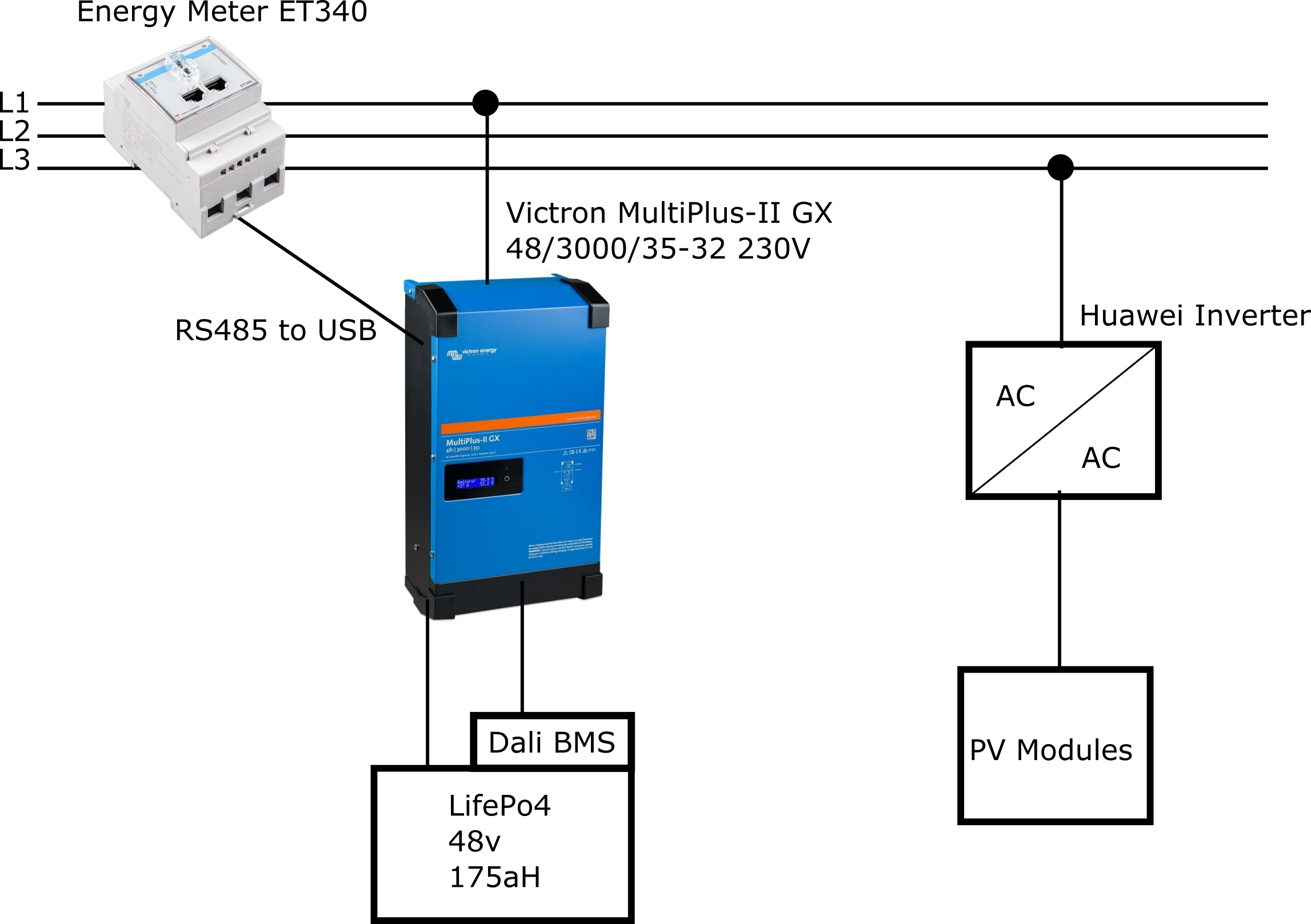
I have a relatively simple Setup:

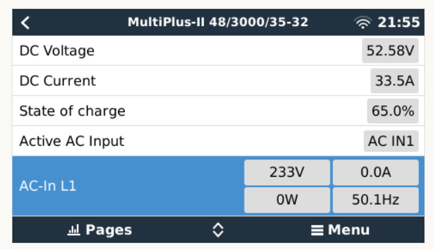
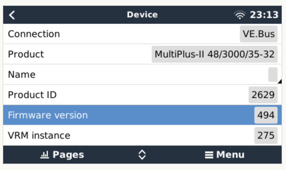
A few years ago I've installed 4,8kW Peak PV System with a Huawai Inverter. Recently I've added MultiPlus-II 48/3000/35-32 GX with a 175ah Battery. A Victron Energy Meter ET340 measures the residual load and provides the information to the victron.

setup-multiplus.png

Purpose / Target:

During the day I would like to store the surplus ov the pv generated energy to use it when there is no PV available or the PV is not capable to feed all consumers.

Configuration:

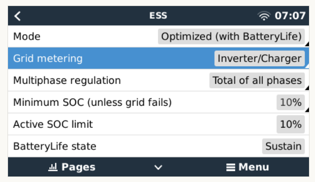
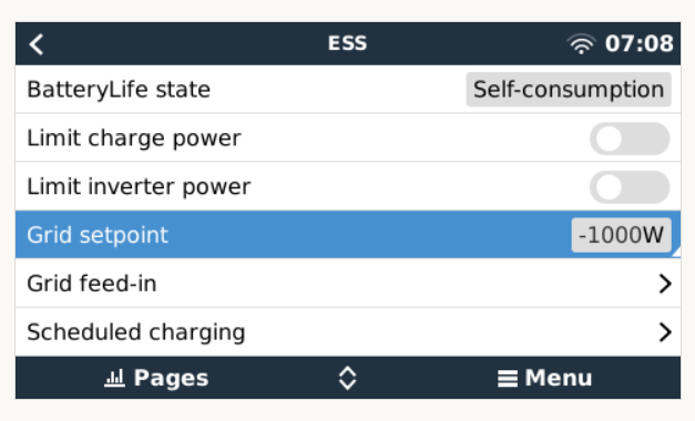
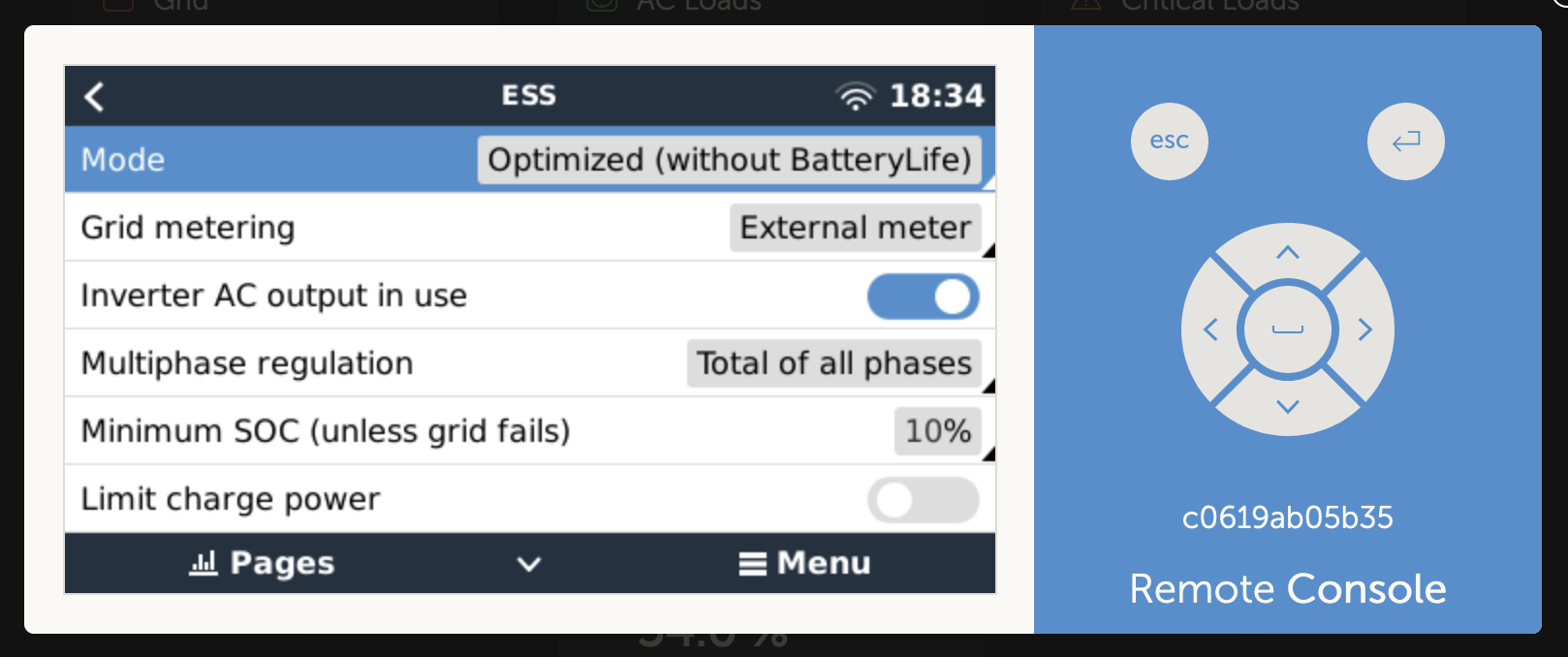
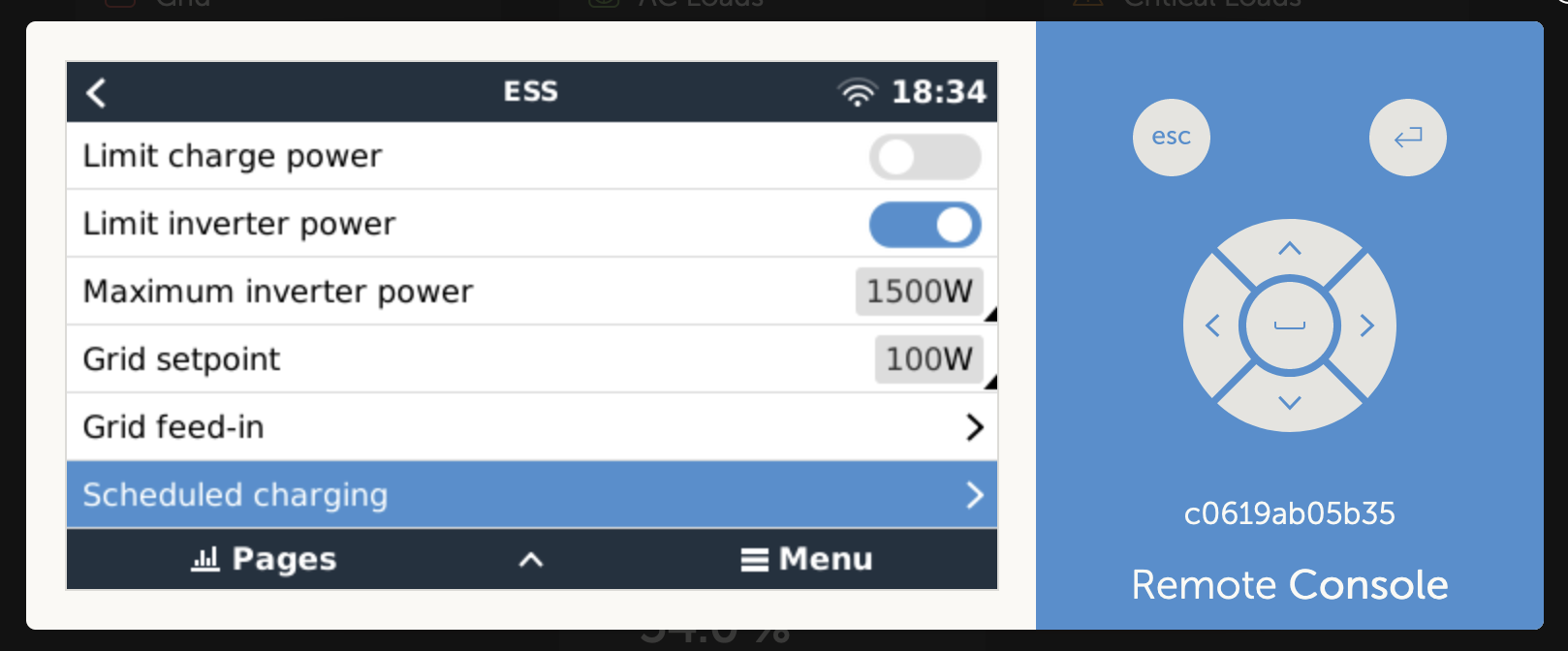
With VEconfigure I've configured the MultiPlus including ESS as shown below.

ess-config-screen-part-1.png

ess-screen-part-2.png

Issue:

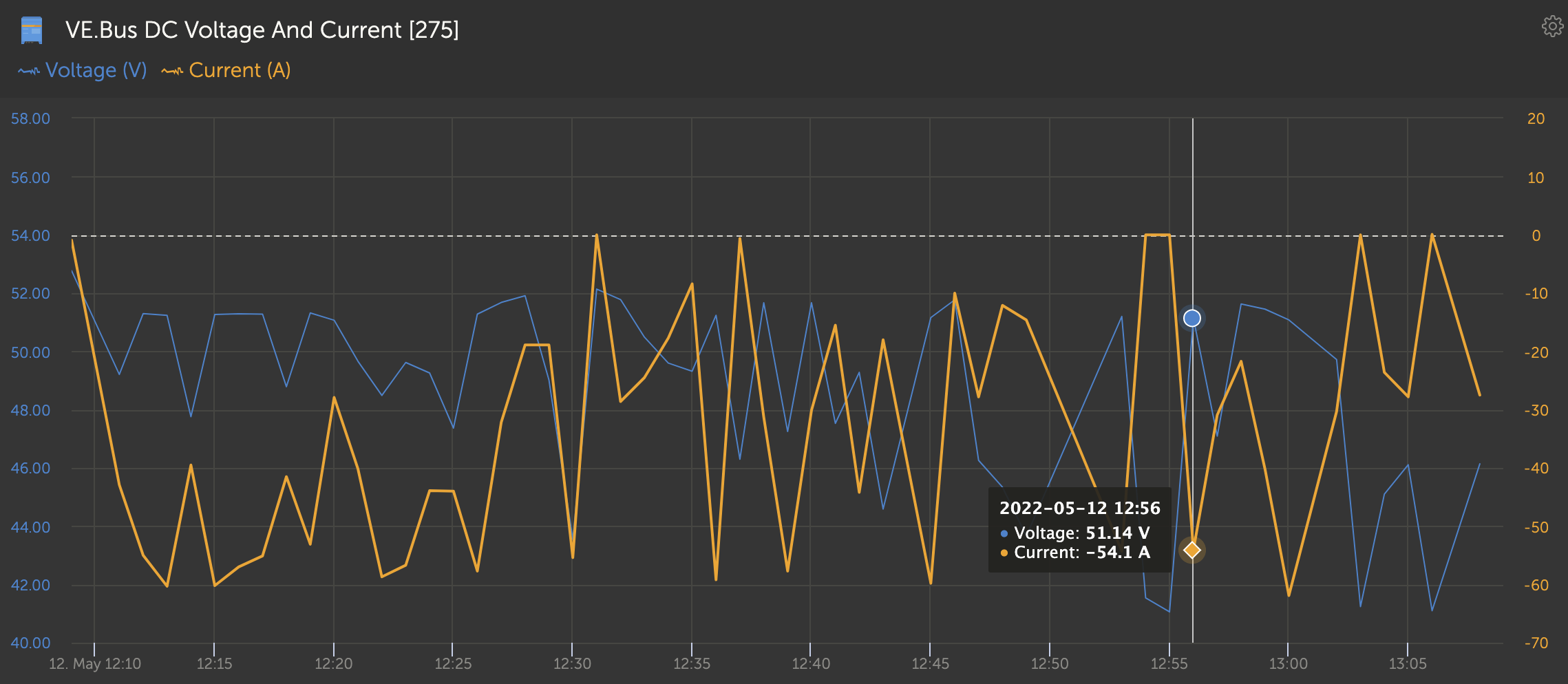
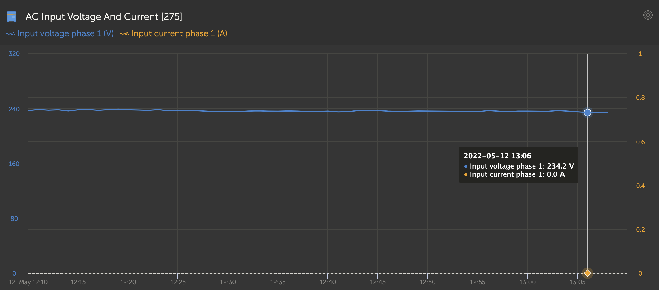
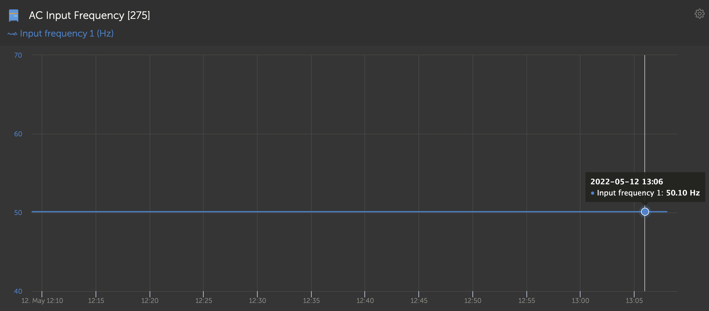
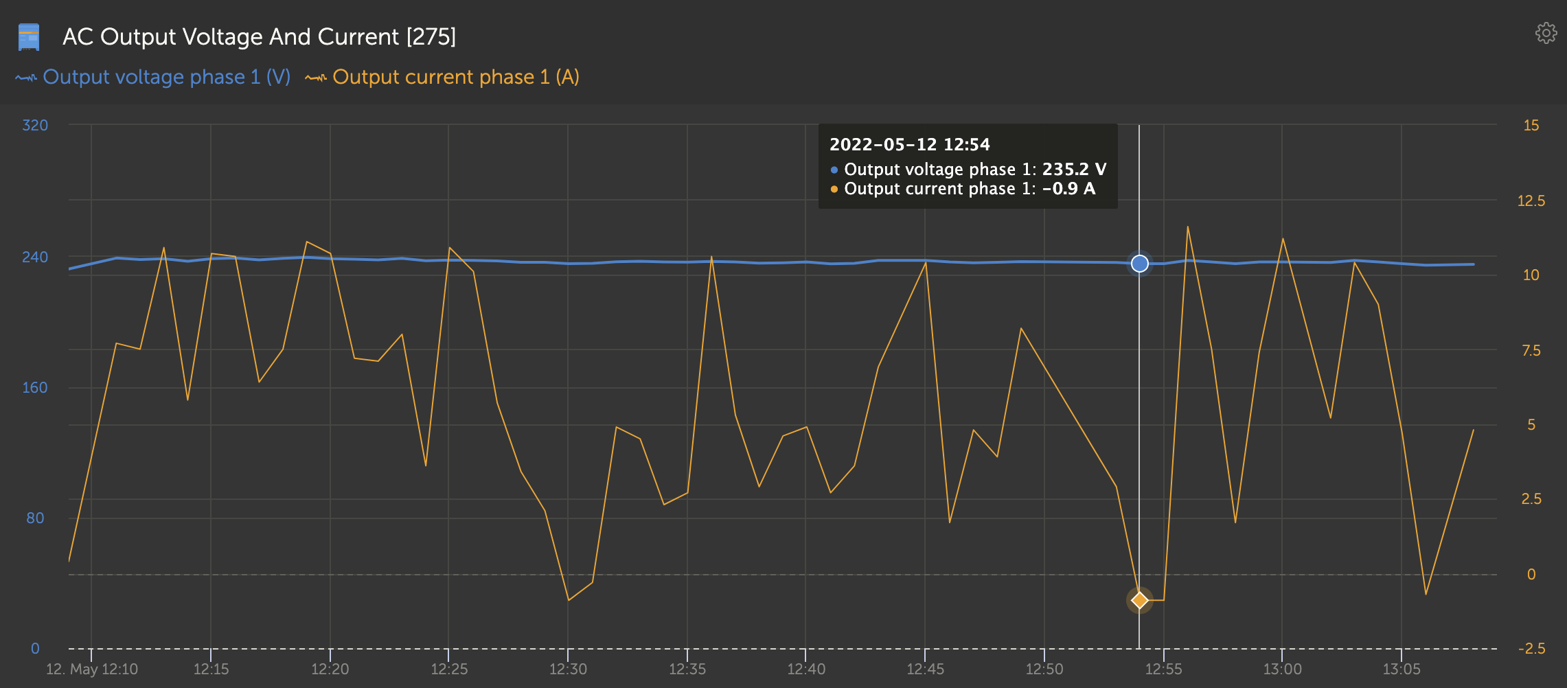
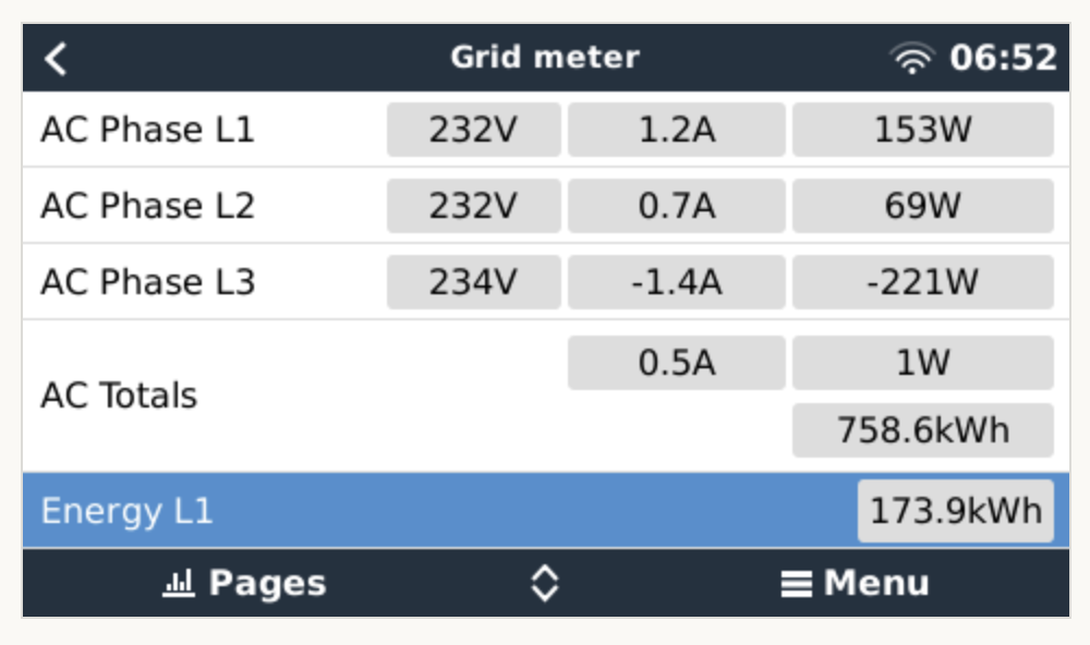
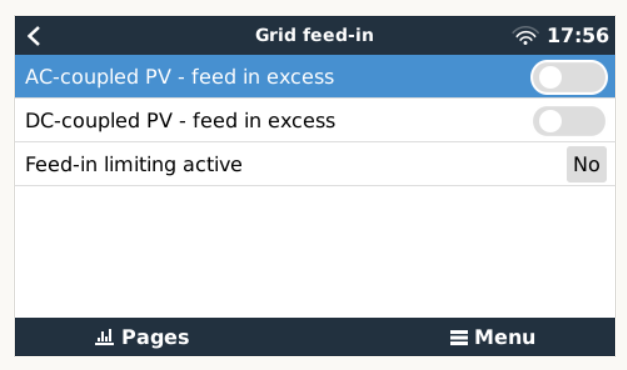
The ESS on the Multiplus is oscillating heavily between charging and discharging. It seems to be that the control mechanism of ESS starts the inverter to reach the grid setpoint in the configuration. This leads to a massive surplus which is feeded into the grid (see first screenshot below). This surplus is registered by the multiplus which then controls into the opposite direction and starts charging the battery (see second screenshot). This load causes ESS to take again the other direction and the cycle starts again. This described issue is independent fromthe Huawei inverter which connected to L3. It is caused even when the Huawei inverter is disconnected.


grid-meter-max-inverter.png
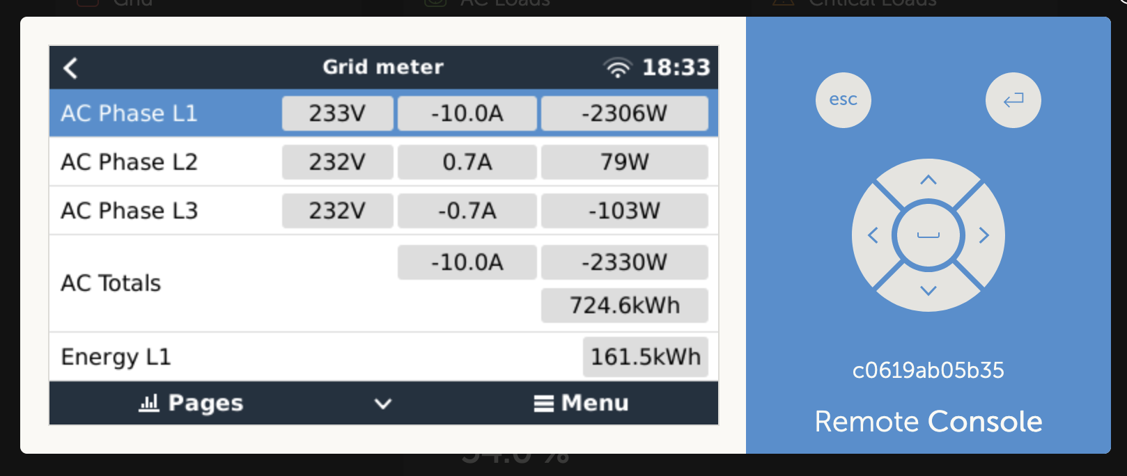
Surplus at L1 due to Multiplus inerter - Feeded into the grid - caused by a ESS


grid-meter-max-charge.png
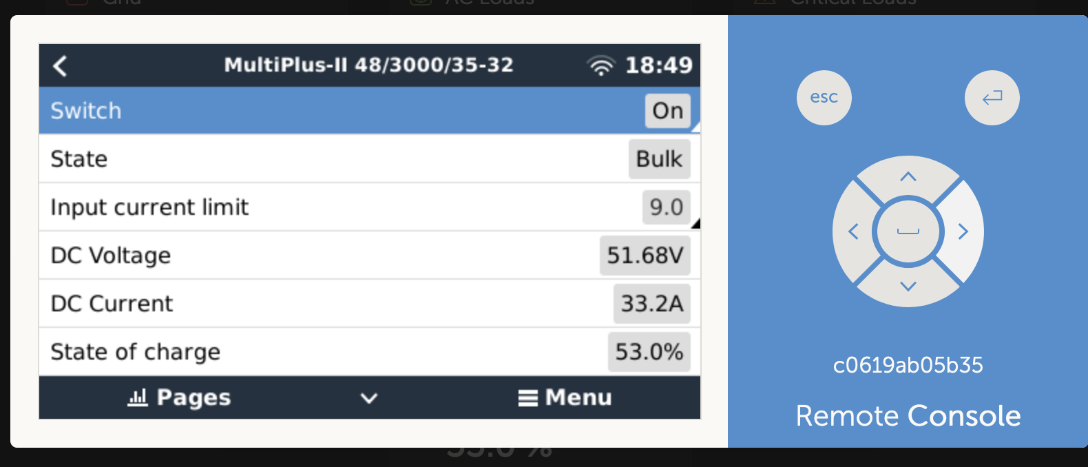
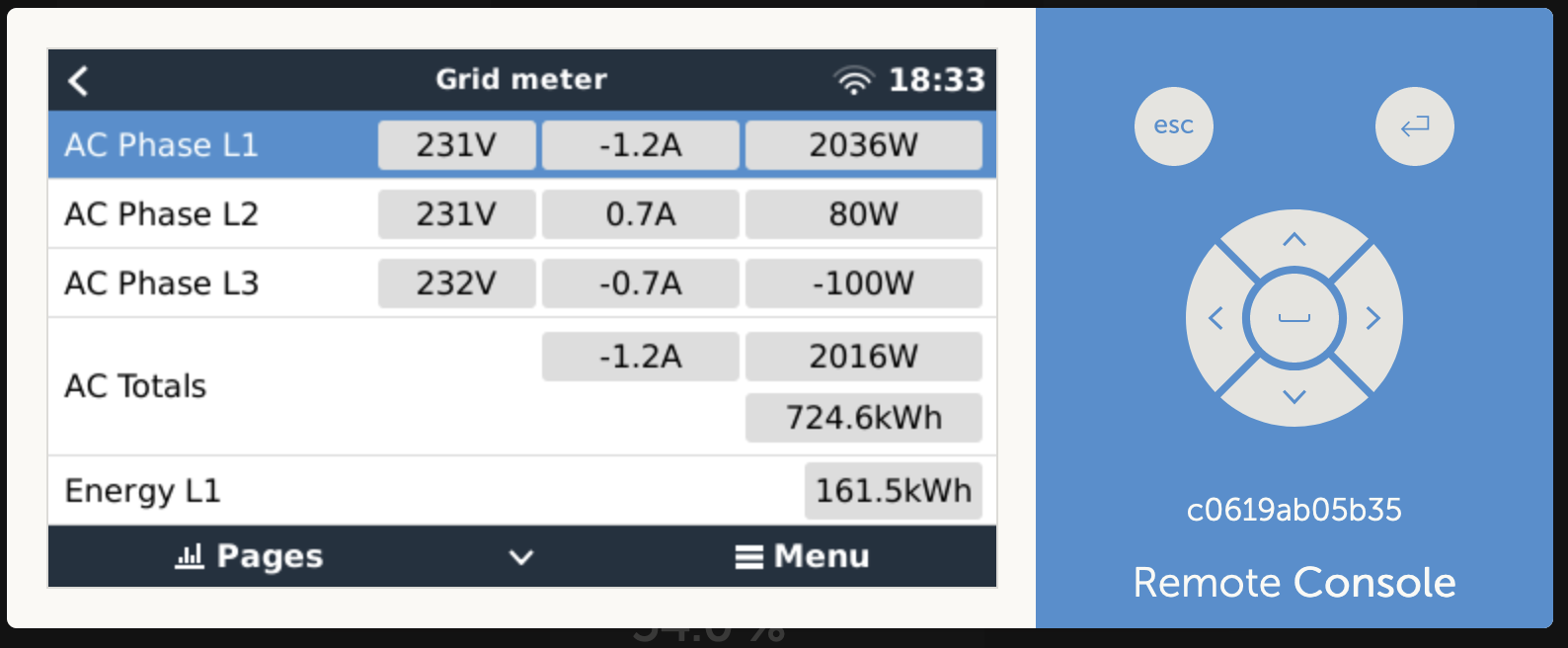
Massive Load at L1 due to Multiplus charging - caused by ESS

Attempts to relief:

I've tried to limit the maximum inverter power within the ESS configuration (see above) and tried to set the AC input current limit. These configurations seem to be ignored or have no inpact to the behavior described above.

ac-input-current.png


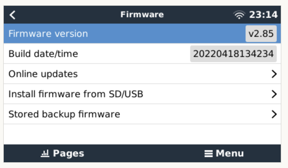
Further Configuration Information:

system-setup.png


ESS
3 comments
2 |3000

Up to 8 attachments (including images) can be used with a maximum of 190.8 MiB each and 286.6 MiB total.

klim8skeptic avatar image klim8skeptic ♦ commented ·
Is your PV inverter really on a different phase to the Multiplus?
0 Likes 0 ·
sascha-brinkmann avatar image sascha-brinkmann klim8skeptic ♦ commented ·

I've tried both. Operating the inverter on another phase and on the same as the MP 2. But even with a completely disabled inverter the behavior is as described above.

0 Likes 0 ·
klim8skeptic avatar image klim8skeptic ♦ sascha-brinkmann commented ·
@Sascha Brinkmann as your diagram is, you are sending any surplus PV energy out to your grid.

And any battery charging is being done on a different phase.

0 Likes 0 ·
8 Answers
Al avatar image
Al answered ·

Hey @Sascha Brinkmann Could the problem be the hardware sensor Jack port? Try plugging a headphone jack in and out a few times like here:

https://community.victronenergy.com/questions/120680/is-anyone-working-on-ac-input-1-not-displaying-any.html

4 comments
2 |3000

Up to 8 attachments (including images) can be used with a maximum of 190.8 MiB each and 286.6 MiB total.

sascha-brinkmann avatar image sascha-brinkmann commented ·

I quick shout our with a huge thanks for your support! This community is crazy and Victron should pay you for your tireless support. It is now working and it was the missing current measurement at AC-in which was the causing factor the oscillation. I don't use a CT clamp but I just followed the hint to plugin and plogout a headphone multiple times at the CT out and voila it's working \o/

The setpoint of 0W is reached and the AC curent is now also shown. I will post a proper answer and close this case later on.

This is MOST definetly a solution to be made available for everyone!

bildschirmfoto-2022-05-13-um-065252.png

bildschirmfoto-2022-05-13-um-065314.png

0 Likes 0 ·
Al avatar image Al sascha-brinkmann commented ·
Glad that worked for you :)


After shaneyake and marekp had exhausted most possibilities and reading your thread I just remembered a comment I'd read from mvader about the plug and found the similar past thread about it.

I'm thinking of suggesting an install of an MPII for a client who's very sound sensitive, so been reading threads lately, sorry to side track, but how do you find the fan / case noise of the MPII?

Cheers

Al

0 Likes 0 ·
marekp avatar image marekp Al commented ·
@Al

If your client is sound sensitive he would probably notice the fan working.

I have 6 MP-II running as 3-phase 2 parallel and it is good thing I installed them in the separate building. :)

0 Likes 0 ·
shaneyake avatar image shaneyake Al commented ·

It really depends on the load as the fan ramps with load.

But you would defiantly want them in a separate room that has a proper door and celling. We normally have them in the house in a utility room made from cinderblock.

The loudest part is disconnecting and connecting to grid, when the contactors fire.

0 Likes 0 ·
sascha-brinkmann avatar image
sascha-brinkmann answered ·

Through another meter I can measure and track the residual load (load of all three phases). As long as the MP 2 is running 6pm until 9:30pm we can see the load which is flipping between max feed in and max charging. Once I've turned of the MP 2 only the resting residual load is left which is a few hundred watt.

bildschirmfoto-2022-05-09-um-072644.png
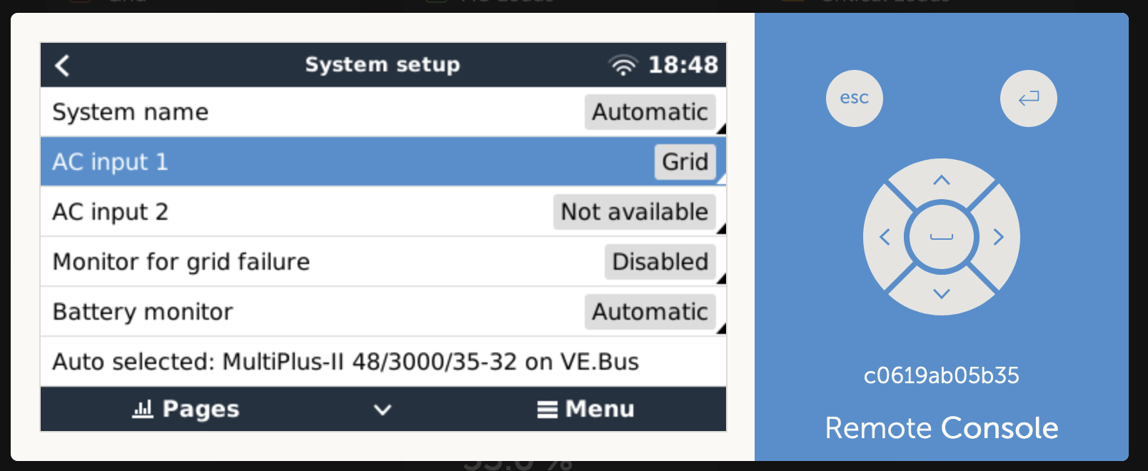
My expectation is that the ESS of the MP 2 regulates to the grid setpoint and not bouncing between the two extrem ends.


2 |3000

Up to 8 attachments (including images) can be used with a maximum of 190.8 MiB each and 286.6 MiB total.

marekp avatar image
marekp answered ·

@Sascha Brinkmann

It would work much better if you had 3-phase PV inverter.

As it is now ESS is trying to maintain grid set point and to do it is using energy stored in your battery. It does not make sense to use it this way.

I would put MP-II and your 1 phase PV inverter on the same phase and set-up the ESS only on that one phase.

6 comments
2 |3000

Up to 8 attachments (including images) can be used with a maximum of 190.8 MiB each and 286.6 MiB total.

sascha-brinkmann avatar image sascha-brinkmann commented ·

In the meantime I've changed the wiring of the inverter and connected it to phase L1 like the MP 2. I'm quite confident that the issue is independent from the inverter since it occurs even when the inverter is disabled.


If this issue is related to the multi phase operation, I'm not able to investigate it. Since it is possible to configure ESS with the option "Multiphase regulation: Total of all phases" I would expect that the ESS measure the sum of all phases and regulates accordingly on the one phase it it connected to. Meaning that charging and feed-in power at L1 causes in the sum of all phases that the "Grid setpoint" is reached.

The solution which I would like to operate is also described within the official documentation: https://www.victronenergy.com/media/pg/Energy_Storage_System/en/multiphase-regulation---further-information.html#UUID-72f5b2fc-0d74-563a-b2d6-848f1e8fd046

0 Likes 0 ·
marekp avatar image marekp sascha-brinkmann commented ·

@Sascha Brinkmann

Change your ET340 settings to single phase operation and select phase L1 (the one with MP-II and PV inverter) and see what happens.

Your current setup will not work properly with 3-phase ESS.

0 Likes 0 ·
sascha-brinkmann avatar image sascha-brinkmann marekp commented ·

The setting "individual phase" doesn't change anything. The issue is still the same and the MP2 chages between charging and discharging continuously.

bildschirmfoto-2022-05-09-um-222238.png

0 Likes 0 ·
marekp avatar image marekp sascha-brinkmann commented ·

@Sascha Brinkmann

You are changing the wrong setting.

You have to change ET340 settings, not ESS settings.

You have to change here:

I have EM24 but you will have ET340 instead.

screen-shot-2022-05-09-at-102753-pm.png

screen-shot-2022-05-09-at-102854-pm.png

If you had EM24 than MP-II and PV inverter must be on phase 2 apparently.

Unless for ET340 is different.

0 Likes 0 ·
sascha-brinkmann avatar image sascha-brinkmann marekp commented ·

Dear Marek. Thans for your support. But I think we're within a dead end. The behavior doesn't change on reconfiguring the meter. The issue is still the same. I'm not confinced that the is related to the metering and more related to the ESS mechanism and its configuration or programmed behavior.


0 Likes 0 ·
marekp avatar image marekp sascha-brinkmann commented ·

@Sascha Brinkmann

Now I can only suggest you to contact the Victron distributor and relay to him your problem.

Good luck.

0 Likes 0 ·
sascha-brinkmann avatar image
sascha-brinkmann answered ·

With activated ESS the the load is not controlled towards the set point. Instead it is oscillating between the max feed in and max charging... All changes like "Multiphase Regulation" and rewiring the inverter don't change anything on the observed behavior.

When there is nothing fundamantelly wrong configured, I get the impression that ESS is faulty and the control mechanism need more dempening or delay controlling the power to be fed or pulled from the grid.


2 comments
2 |3000

Up to 8 attachments (including images) can be used with a maximum of 190.8 MiB each and 286.6 MiB total.

marekp avatar image marekp commented ·

@Sascha Brinkmann

Is your Venus software at version 2.80 or later?

Note there was an adjustment to this feature in Venus 2.80, this manual reflects the behavior from that version and later.

Single phase ESS in a system with a three-phase connection to the utility grid

Single phase ESS is a single inverter/charger.

  • "Total of all phases" selected - ESS regulates total power L1 + L2 + L3 to 0.

  • "Individual phase" selected - ESS regulates only the power of L1 to 0.

0 Likes 0 ·
sascha-brinkmann avatar image sascha-brinkmann marekp commented ·

I've updated the MP 2 GX shortly after receiving it (see screenshot below). Beside the MP 2 itself and the energy meter, I don't operate any further Victron devices.

bildschirmfoto-2022-05-09-um-231330.pngbildschirmfoto-2022-05-09-um-231409.png

0 Likes 0 ·
joshyjs avatar image
joshyjs answered ·

You have nearly similar configuration like me.

( Geht notfalls auch deutsch... )

Last week I also asked what is to set. Now for me it works.

If you want further help I can offer to set me as user.

Im able to check all settings. Also with the remote software.

Oscillating I had when I set it to load only.


Without battery live is right.

Under Devices-Grid Meter-Setup-Phase configuration set to 3p.n

ESS you set to Sum of all phases

Below of this setting you find grid feeding ( Netzeinspeisung ).

In this setting you set all off. AC and DC PV. .


Why? This to understand is tricky.

If you set anything here to ON means you have a PV system behind the Victron.

On AC output 1 or AC output 2 or via DC in the DC Battery bus.

But you don't have. Your PV has nothing to do with your Victron system.

It's parallel.

Your Victron has to be connected to AC in. Nothing else.


You want your Victron to load the battery when there is enought to feed the net.

And you want it to take all power what is possible until max charge of 32A DC.

The EM24 (340?) has only to measure the amount and direction of the power.

Irrelevant from which source the power to the net is generated.

Can be a PV system or a generator...

When Battery will be charged with max A the remaining power feeds the grid.

( If you want to feed the net. If you don't want zero export. )


I expect you still have wrong settings.


2 comments
2 |3000

Up to 8 attachments (including images) can be used with a maximum of 190.8 MiB each and 286.6 MiB total.

sascha-brinkmann avatar image sascha-brinkmann commented ·

Dear joshyjs,

this sound very promising! I'll try your setting this evening and let you know. If I wouldn't get any further I would reach out to you and arrange a joint configuration session :)

Best regards / Viele Grüße,
Sascha

0 Likes 0 ·
sascha-brinkmann avatar image sascha-brinkmann sascha-brinkmann commented ·

Let's stick to english for the moment. When we can solve the issue there is an broader audience who can benefit from the solution.

First I've checked the config at ESS --> Grid feed-in

screenshot-2022-05-10-175709.png
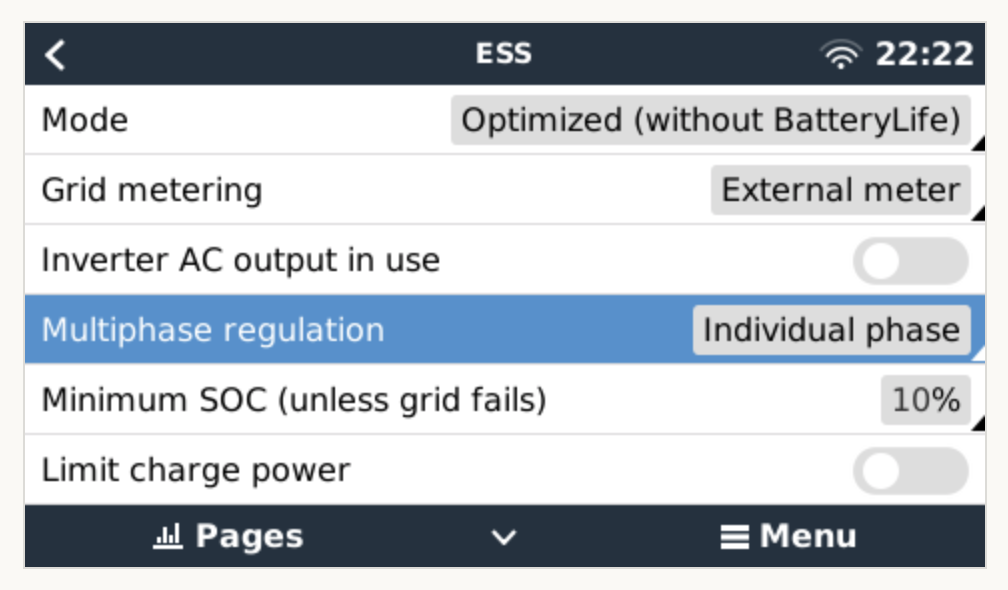
The meter configuration looks like this, which is basically 3-phases + neutral

screenshot-2022-05-10-180005.png

What else can I check, because the oscillating even happening with the parameters which you've asked to validate.

Dear Joshyjs, your support offer is much appriciated. How can we follow up directly? Do you would like to reach to me exchaning contact details:
sascha.brinkmann <at> gmail.com

0 Likes 0 ·
shaneyake avatar image
shaneyake answered ·

You can try changing the grid meter to Multiplus in the ESS menu.

Then set the grid setpoint to -1000W and see if that runs perfectly or not.
This will help locate the problem.
Can you post a screenshot of VRM advanced data, VE.Bus Inverter Input Current, Voltage and Frequency?

12 comments
2 |3000

Up to 8 attachments (including images) can be used with a maximum of 190.8 MiB each and 286.6 MiB total.

sascha-brinkmann avatar image sascha-brinkmann commented ·

I've configured ESS as following to figure out if the ESS is capable to supply constantly a defined value. I did it as following:

screenshot-2022-05-11-070739.png

screenshot-2022-05-11-070809.png


The result is not that promising. This is the feed-in power after I've set the settings. The PVinverter was disabled at this point of time.

screenshot-2022-05-11-071159.png

I've also tried to use the opposite direction and not discharge but to charge the battery. There I've choosen 200W. The charger power was way above the defined value.


0 Likes 0 ·
shaneyake avatar image shaneyake sascha-brinkmann commented ·
Are you sending data to VRM?


I would like to see the voltage, current and frequency over time. I believe the inverter might not have a stable grid connection which can cause this behavior.


On the advanced tab on VRM, you can add widgets which allow you to plot all the values of your system overtime.

0 Likes 0 ·
sascha-brinkmann avatar image sascha-brinkmann commented ·

I've captured the requested data. Here are the results. To capture them, I've disconnected the PV Inverter, the Energy Meter ET 340 and set the Grid Meter within ESS to Inverter/Charger. The setpoint was put to 500W feed-in.

bildschirmfoto-2022-05-12-um-131041.pngbildschirmfoto-2022-05-12-um-131010.png

bildschirmfoto-2022-05-12-um-130956.png

bildschirmfoto-2022-05-12-um-130943.png

0 Likes 0 ·
shaneyake avatar image shaneyake commented ·

From the data below, it looks like you input current sensor is not working.
Can you go to the inverter on the GX and see if you get a reading on input current or watts?
If the input current sensor is not working then ESS will never work and the inverter needs to be repaired.

Do you have a way to measure the AC input current, like with a clip on meter? Do you have a CT attached to the Inverter?

0 Likes 0 ·
sascha-brinkmann avatar image sascha-brinkmann shaneyake commented ·

You're right the current forAC-In is zero and zerefore the wattage is as well. Do you think this is a defect of the Multiplus 2?
screenshot-2022-05-12-215608.png

With the clamp ampere meter I can measure a current, but this obvious since the Multiplus is feeding into the grid as it drawing power from the battery (see above).

0 Likes 0 ·
shaneyake avatar image shaneyake sascha-brinkmann commented ·

Just to confirm the clamp meter is on AC input Live and you are getting a reading and the inverter is displaying 0.0A?

There is little headphone jack labeled CT on the bottom of the inverter, nothing is plugged into there right?

If that is the case, I would contact your distributor for an RMA as you have defective unit.

0 Likes 0 ·
marekp avatar image marekp shaneyake commented ·

But why it did not work properly with external ET340?

0 Likes 0 ·
shaneyake avatar image shaneyake marekp commented ·

The gx commands an input current setpoint to the inverter. It does not command an inverter power but rather the power on AC input and the inverter regulates that internally. Without the AC input data the inverter will bounce off it's limits.


There is also no current sensor on the AC_OUT this is a calculated value

(I know some older inverters might have this sensor but new ones don't)

It is calculated as INVERTER_POWER + AC_Input = AC_Output


You can actually see the oscillations in the output current data. The data is very low sampling rate else you would actually see the full oscillations.

0 Likes 0 ·
marekp avatar image marekp shaneyake commented ·
So the problem is with a GX control and not the CT internal or external.
0 Likes 0 ·
shaneyake avatar image shaneyake marekp commented ·
No, it is the Inverter input current sensor.

Sometimes the CT jack is damage and it can causes this problem or a CT that isn't installed in the correct location.

From the data above it is clearly an inverter regulation problem.
This can be grid related but in this case the input current is always 0.0A which is not possible when grid connected as you will always have some push and pull when running.

0 Likes 0 ·
marekp avatar image marekp shaneyake commented ·
My "but" again. I hope you do not mind.

When he used external ET340 the grid currents were not 0A.

GX had proper information only its "control" signals where "not understood" by MP-II.


0 Likes 0 ·
shaneyake avatar image shaneyake marekp commented ·

Grid Current and Input Current are not the same right. These are currents in different locations.

The inverter is producing these oscillations, we can see on both the Battery currents and AC_Out that the inverter is producing power. When the inverter produces more than loads we get export which is picked up by the ET340.

You are correct, the GX has the correct data and is mostly likely sending the correct values to the inverter. The inverter just has no feedback so internally it is hitting a limit and then reseting and then hitting a limit, over and over.

If you read my comment from 4 hours ago, starting with
"The Ramp rate limit is 400W per second" I try to explain how the ESS control actually works.
https://community.victronenergy.com/questions/51697/victron-ess-et112-slow-response.html

0 Likes 0 ·
joshyjs avatar image
joshyjs answered ·

I still guess there are wrong settings in the software layer.

You can only change this via VRM Portal remote or by a converter dongle.

Both with VE Configure tools.

I sent you aan email. Pls check...

2 |3000

Up to 8 attachments (including images) can be used with a maximum of 190.8 MiB each and 286.6 MiB total.

maboth avatar image
maboth answered ·

I have the same effect. My question is: https://community.victronenergy.com/questions/136049/critical-load-shows-high-values-how-can-i-check-th.html

Can you check the displayed critical load? Don't connect wires. Just switch on to see what the display panel shows. I reduce the charger to 1A and the inverter power to 300W and it works but not well. With that values I can run the system and test to find the bug.
I know a similar system and I have seen that it is working. So there must be an error we don't see.

1 comment
2 |3000

Up to 8 attachments (including images) can be used with a maximum of 190.8 MiB each and 286.6 MiB total.

maboth avatar image maboth commented ·
Ok. The solution is the 3.5mm jack trick.
0 Likes 0 ·