question

t1-terry avatar image
t1-terry asked

Programming the AUX relay to turn on/off with the fan

I have a Multiplus 12/3000/120 that I have installed in a European motorhome. There isn't a lot of room and the walls are heavily insulated resulting in the enclosure getting hot and the heat rising up into the motorhome.

I have installed an addition fan to pull the hot out out of the enclosure and I'm trying to program the relay driver/s to turn the additional fan on when the inverter fan turns on.

I've read through the other answers but I can't relate them to this inverter.

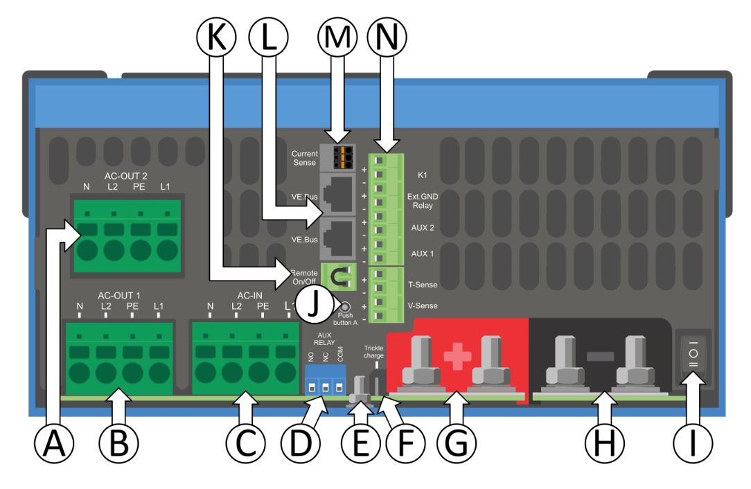
The only relay drivers appear to be AUX 0/1 beside the voltage sense input terminal and is marked with + and - on each terminal. The other relay driver is in the top right corner marked NC NO COM.

I programmed via the assistant to switch the main relay driver on within 10 secs of the fan turning on, loaded it to the inverter but I still can't get either relay drivers to switch state when the fan is running or not running ...... what am I doing wrong?


T1 Terry

fan
2 |3000

Up to 8 attachments (including images) can be used with a maximum of 190.8 MiB each and 286.6 MiB total.

5 Answers
bathnm avatar image
bathnm answered ·

Hi, how have you physically wired this? I would personally use the relay top right (programable relay). Wire a positive feed into the common terminal. Then wire the fan + to the normally open terminal and fan negative to the negative buss. That should do it.

Do not use the Aux relays as they are signal / dry contact relays and not designed to take any power.

1 comment
2 |3000

Up to 8 attachments (including images) can be used with a maximum of 190.8 MiB each and 286.6 MiB total.

tim-henderson avatar image tim-henderson commented ·

For clarity sake, how do you suggest wiring a small fan? Do you mean wire the positive feed into the COM port on the Aux relay and then the fan + and fan - to the K1 terminals?


multiplusii-diagram.jpg

I/O Terminal, from top to bottom:

  1. 12V 100mA
  2. Programmable contact K1 - open collector 70V 100mA
  3. External ground relay +
  4. External ground relay –
  5. Aux input 1 +
  6. Aux input 1 –
  7. Aux input 2 +
  8. Aux input 2 –
  9. Temperature sense +
  10. Temperature sense –
  11. Battery voltage sense +
  12. Battery voltage sense -
0 Likes 0 ·
Matthias Lange - DE avatar image
Matthias Lange - DE answered ·

What MultiPlus do you have exactly (part number)?

AUX are inputs not outputs.

Depending on what. MultiPlus you have, you have only the "primary relay" (in the top right corner of the PCB) or you three relays (primary, K1 and K2).

2 |3000

Up to 8 attachments (including images) can be used with a maximum of 190.8 MiB each and 286.6 MiB total.

bathnm avatar image
bathnm answered ·

Yes you need one to switch in and another too switch off.

2 |3000

Up to 8 attachments (including images) can be used with a maximum of 190.8 MiB each and 286.6 MiB total.

t1-terry avatar image
t1-terry answered ·

Thank you for the quick replies, still finding my way around this forum so didn't see the replies to my question.

The part number is PMP122300001.

You answer that aux are input not output saves me trying to get that one to do what I want.

It appears I only have the primary relay in the top right hand corner. I programmed the relay to switch on when fan switches on using the assistant, do I need to add a second action for the assistant to turn the relay off?

I tried the relay contact using a continuity test on the multi meter but it didn't switch to relay open when the fan stopped.

Thank you for your help so far


T1 Terry

1 comment
2 |3000

Up to 8 attachments (including images) can be used with a maximum of 190.8 MiB each and 286.6 MiB total.

Matthias Lange - DE avatar image Matthias Lange - DE ♦ commented ·
Yes you always need at last one assistant to switch the relay on or off.
0 Likes 0 ·
t1-terry avatar image
t1-terry answered ·

That explains why I couldn't get it to switch between on and off. That job has already left the workshop, ended up fitting a programmable thermostat with the sensor in the air out vent at the top of the inverter and that seemed to do what was required .... also dropped the mains charging current down from 90 amps to 50 amps and that lowered the over-all enclosure/inverter temp .... between the two "fixes" the customer was happy and that was the main aim :lol:


Still learning about the abilities the assistant has, in future I'll look for the inverter models that have more relay output points and look for items that the assistant can switch on/off.


T1 Terry

2 |3000

Up to 8 attachments (including images) can be used with a maximum of 190.8 MiB each and 286.6 MiB total.

Related Resources

Additional resources still need to be added for this topic