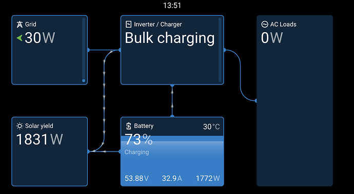
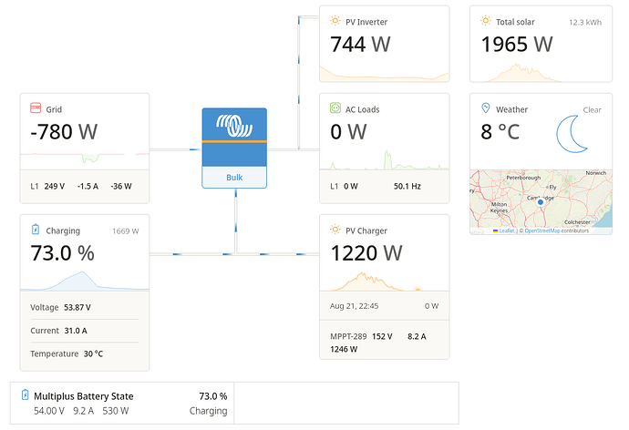
I have a setup with AC and DC coupled panels, like this:
It has been operating for 8 months or so with just the grid CT clamp, so the AC inverter output was not measured. Things worked remarkably well, and the multiplus controls the export so that the AC PV power goes into the house and battery unless export is requested.
I finally got my ET112 working so now I can actually measure my total PV output (rather than estimating total PV from just the DC side).
I configured things like this:
Position of AC Loads: AC Input and Output
AC Input 1: Grid
AC Input 2: Not available
ET112: Role: PV Inverter
Position: AC Input 1
And the Cerbo display worked as expected, but the VRM display show the wrong grid export value. It shows ‘real export’+’AC Inverter power’.
Why would they be different? And why is VRM showing phantom export, when that AC PV power is actually going to the house and battery? And it has a clamp at that point so it knows what the real value is.
I found various other reports of this problem, so it has been present for at least a year.
One of those posts explained that if you set position: ‘AC output’ for the ET112 (even though it is on the AC Input), then VRM shows the correct grid export (and now matches the Venus gui). And indeed this is true.
For completeness, the behaviour doesn’t change (i.e export stays wrong) if you set
Position of AC Loads: AC Input
and/or
ET112: Position: AC Input 2
Does anyone know what’s going on here? Surely VRM and Venus OS GUI should never disagree in such a significant way? And have I just misunderstood something or this actually the bug it seems to be?


