I have my grid setpoint in ESS set to +10W. The GUI shows this regulating correctly at around 0W from grid. When I look at the VRM however I see the below.
The L1 detail shows -2W but the value above shows -446W. If that’s the Apparent Power it’s surely in the wrong place?
This system is grid-parallel on L1-In. No loads on AC outs. MP2 5000VA, single phase.
Some further info. This discrepancy seems to be caused by the AC PV Inverter power reading (connected to AC-In with all AC loads). When the PV power increases it shows this as negative grid power but only on the VRM. The grid power shown on the local GUI is fine and remains controlling around 0W.
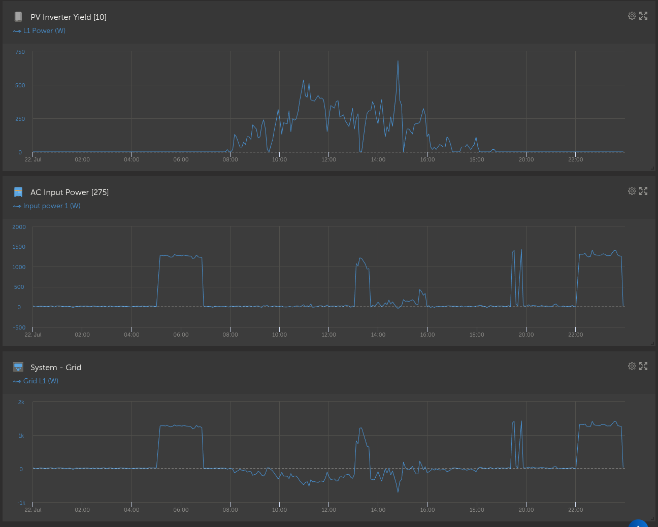
Advanced VRM graphs below show “Grid” and “AC Input Power”. I’m not sure what the difference is between these but “AC Input Power” seems to be my true grid power (measured with a 3rd party meter). “Grid” for some reason is being dragged negative by the influence of the PV Inverter power value.
And just to further clarify the issue… The below shows the system with ESS turned off. The Grid power value in the VRM shows -47W which is incorrect. The correct value is shown in the Grid info box for L1 (230W). The 230W was proved to be correct using a 3rd party meter.
Does anyone know why I’m seeing this rogue value in the VRM? The local GUI shows the correct (230W) grid power so I’m at a loss to explain it.
The issue is with the configuration of the AC Current Sensor Assistant. When asked to set the location of the PV inverter, I chose “PV inverter coupled on AC input 1 of this phase” because my PV inverter is connected to AC-In-1 along with all the other AC loads (grid parallel mode). Nothing is connected to the AC outputs.
In this configuration, the system should calculate AC loads power as GRID + PV + INVERTER but it doesn’t. It fails to add on the PV power to the AC Loads power.
It also (strangely) subtracts the PV power value from the grid power value (but only on the VRM, the GUI shows grid power fine??). All very confusing!
Anyway, the “fix” was to re-run the Current Sensor Assistant and set the PV Inverter location to “PV inverter on output of this phase” which is technically incorrect but the system now treats the PV inverter as supplementing the AC loads and so the correct AC Load value is displayed.
In this configuration the Grid Power in the VRM is also correct. This appears to be a bug that I hope will be resolved in the future.