New regulation: Active power setpoint – How to implement externally controlled zero export with ESS

Hello, what options are available for implementing the network operator’s new „active power setpoint“ requirement (Austria) in an ESS configuration?

Essentially, the network operator needs the ability to remotely set the feed-in via an LSG (= load switching device / ripple control receiver) to zero, e.g. when too much power is being fed into the grid.
The LSG switches a contact (normally open), which then has to be connected via an interposing relay to all generating systems so that the feed-in can be set to 0.

Unfortunately, I only recently became aware of this new requirement. However, I am already in the final phase of wiring and commissioning my system, which has the following main components:

  • 1x Cerbo GX 2 plus display
  • 3x MultiPlus 2 48/5000 → in a 3-phase configuration
  • 1x Smart RS 450/200
  • 16S batteries controlled via CAN BMS
  • Lynx
  • 3-phase microinverters from Hoymiles

Simplified representation of the system’s AC configuration:
Meter distribution board downstream-of-meter fuse → sub-distribution board AC-in of the 3 Multis → all loads and microinverters are connected (with the appropriate fuses/RCDs) to AC Out 1 of the 3 Multis. The Multis can be bypassed in the event of servicing by means of a „Grid-0-Emergency“ bypass switch. Normally, the switch is always set to „Emergency“.

What options are available for implementing this remotely controlled zero-export function in an ESS configuration?

One approach would be to use „ESS in Mode 3“ to set „Feed-in“ to zero, triggered via an interposing relay!?? Does that work? Are there any other approaches that have already been tested in practice?

Once the feed-in restriction is lifted again (= the LSG signal is no longer active), the ESS should function normally again and be able to feed power into the grid.

In the Austrian grid code, AUX 1 is provided for this purpose.
This makes the MultiPlus set the feed-in to 0, but your microinverters are NOT controlled via it.

Thanks for the help!

Right, so for zero export, on the Master L1, AUX1 + and - need to be connected to the volt-free normally open contact of the coupling relay controlled by the ripple control receiver.

If necessary, the microinverters could be disconnected on the main power side via a contactor.

Addition:
Regardless of which mode the ESS is used in, is there nothing else that needs to be configured or adapted!?

If the grid operator specifies zero export, do all the other ESS functions remain available, such as charging/discharging the battery, inverting for loads, …?

@All:
The description of the analogous topic for zero export (and charge power limitation) in Germany can also be found here:
VE.Bus v555 released - genset compatibility and German §14a EnWG - Victron Professional

Herstellerklärung-und-Anschlussplan-§14a-EnWG-und-§9-EEG.pdf

Thanks, WLV (active power setpoint = 0) is now clear with AUX1!
The systems are often more complex, though—for example, with additional FRONIUS inverter(s). How is the control handled in this case?
Are Fronius inverters integrated into the Victron system also automatically “curtailed” when the MP-II AUX contact is closed (either on AC in and/or AC out)?

Please advise—thanks!

Hello Thomas,
the Fronius probably isn’t controlled by the GX. This has come up here before, but unfortunately I can’t find the sources.
Only DC-coupled MPPTs are regulated, and even then only via the Multi’s own sensors, so only ACout. The grid meter is ignored in the process.
You could switch the Fronius off via its own inputs.
Or you could do it with Node-RED and the inputs on the Cerbo. Whether that will be accepted or not, nobody knows as long as no one asks how it works……

According to the ESS Installation Manual:

4.3.14. AC-coupled PV – Zero and limited feed-in with Fronius AC PV
AC-coupled zero or limited PV feed-in is specifically designed for and extensively tested with Fronius AC PV inverters.

• The oldest Fronius firmware version that can be used is 3.7.3-2
• If more than one Fronius PV inverter is present in the system, they will all be limited
• Zero feed-in is not supported with Fronius IG Plus inverters.
Change the following settings in the Fronius web interface:
• In the Fronius Setup menu (code 73887), set data export via Modbus to tcp.
• In the same menu, set the Sunspec model type to int + SF.
• Under Settings→DNO Editor, make sure that “Controlling via Modbus” is set to priority 1 in the “Controlling priorities” section.

Controlling priorities
1 - Controlling via Modbus
2 - IO control
3 - Dynamic power reduction

Note: Under Settings→DNO Editor, the default setting for dynamic power reduction is “No limitation / Off”. If the Fronius is supposed to stop generating power when communication is interrupted (and it no longer receives instructions from the Modbus control), “Dynamic power reduction” must also be configured.
For this behaviour, set the export limitation to “entireSystem” and DPL_SOFTLIMIT_POWERLIMIT to the export power limit (or 0).

Dynamic power reduction

Export Limitation o off x entireSystem o weakestPhase
wattPeakReferenceValue | 20000 |
o DPL_Hardlimit
o DPL_Softlimit
DPL_Softlimit_Powerlimit | 0 | | W |
o Reduce inverter power to 0% if meter connection has been lost

Then check whether all the criteria listed above have been met. “Feed-in limiting active No” (feed-in limit active: No) is displayed if the required firmware, data export or Sunspec model type settings are incorrect, if the devices are switched off (no PV available), or if the AC input is switched off / unavailable.
During normal operation, “Feed-in limiting active Yes” (feed-in limit active: Yes) is displayed.
Do not use a Fronius Smart Meter for export limitation if it is part of a Victron ESS system. Further details about when a Fronius Smart Meter can and cannot be used are explained here.

I strongly recommend reading the original text: => ESS Installation and Configuration

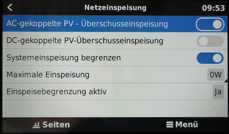
I am currently implementing this myself and have simply connected a switch to AUX 1 of the master Multiplus2. The MP2s respond to the signal, although not yet as they should. Some settings on the Cerbo will probably also need to be changed or adjusted. In particular, the following items in the ESS menu: Grid feed-in and Grid setpoint. I am not yet entirely sure where which values need to be entered.

Basically, when the battery is full and there is sufficient energy for my loads, I want the available surplus to be fed into the grid within the feed-in limit permitted by the utility company (currently 4 kW in my case), regardless of whether it comes from the Victrons or the Fronius (AC coupling, DC coupling). Somehow, I still cannot quite get this to work; the values shown on the display do not make sense to me. It is also still unclear to me what limiting inverter power means.

PS: The system has not yet been approved and is currently in test operation, so the maximum feed-in is currently set to 0 watts.

If the Fronius is on the same LAN as the Cerbo, then it is indeed controlled via Modbus.

Of course, the appropriate settings must first be configured on the Cerbo, although I don’t have them to hand at the moment.

Yes, the Fronius is controlled via Modbus by the Cerbo when everything is configured accordingly, but not via the Aux input on the Multi (feed-in limitation). This signal is NOT forwarded via Modbus.

You can only set a fixed limit for grid feed-in on the Cerbo; DC and the Fronius (when configured) will then be throttled….

Be careful! Fines could be imposed here even if zero feed-in is configured. I recently received a letter from my utility company informing me of this.

What kind of Fronius do you have … or what output does it have?

You can limit the MP II via the system feed-in setting or by setting the MP II’s maximum output … it depends on your setup.

And if you’re only allowed to feed 4 kW into the grid … why so many solar panels? Do you have such a large household load?

So, here’s a brief overview of my installation — 3-phase system

2 Victron RS450/200 solar charge controllers

3 MultiPlus II 5000s, Cerbo, display

1 Fronius Symo 5.0-3-M

6 Pylontech US3000C

The Victron and Pylontech units are located in a dedicated plant room, while the Symo is in a garage around 20 m away.

The reason for the 19.1 kWp is, on the one hand, my high electricity consumption and, on the other, the fact that the whole system produces very little in winter anyway. That’s why I also find it somewhat pointless to use peak output as a parameter when it can never be reached in our part of the world. For purposes such as assessing the connection capacity, the active power output of the inverters should be used instead, as this would be fairer.

Hello Kurt,

The zero-feed-in limitation via the Multi’s Aux input only works with loads connected to the Multi’s output, and only the MPPTs are throttled.

…unfortunately.

Hmm, the ESS installation manual says something different …

I’ve now configured the Fronius via the web interface (although you’ll need to have the passwords for this yourself). I think the function also depends heavily on the control priorities set in the EVU editor. Modbus MUST be entered as the highest priority there. Unfortunately, I can’t test it any more today — there isn’t enough sunlight left. I’ll post a screenshot of my settings here:

I’ll test it tomorrow; I’m really hoping this works. If not, the only option left is unfortunately to use contact multiplication, although IO control will presumably have to be set as the highest priority then.

hello,

the ESS manual seems to be referring to the grid setpoint when you set it to 0. However, that is something different from controlling the Multis via the Aux1 input.

but you can connect the signal to an input on the Cerbo and then use Node-RED to set the grid setpoint to 0.

cheers

If you set it on the Cerbo under ESS/Grid feed-in/4 kW, it works so that no more than 4 kW is fed into the grid.

The grid operator probably wants this setting to be available on the inverter under the country settings … protected by a password. Unfortunately, that isn’t possible.

If you’re reasonably comfortable with Node-RED, you can also set the desired maximum grid feed-in value when an input on the Cerbo is triggered.

That way, he can feed up to 48 kWh into the grid per day. You need a lot of solar peak capacity for that.

For example, I have 5.4 kWp of solar modules, but only an MPII-3000 and an old 600 W balcony power station, so I can feed in a maximum of 3,000 W at any one time. However, by setting the “Grid setpoint” in the ESS to, say, 400 W, I feed at least 400 W into the grid around the clock in summer—and with a full battery and plenty of sunshine, even up to 3,000 W. The “Grid setpoint” is simply set so that the battery only reaches 100% SOC in the late afternoon or early evening. This means that, despite the inverter’s limited output, I can feed the entire surplus from my 5.4 kWp into the grid.

Hi Matthias

Just a quick note again: I’m from Austria, in the NetzNÖ (EVN) supply area.

(Quote from integrating Fronius Symo into an ESS on AC-Out)

My Fronius is connected to AC-Out1, with the country code set to Austria. A few weeks ago, I noticed that the charging voltages for my Pylontech batteries (15S!) behaved unusually in off-grid mode, with spikes of over 56 V being produced — not exactly safe for the cells. After a phone call with an acquaintance, I changed the grid code set on the Fronius Symo 5.0-3-M from Austria to MG50. The spikes have not occurred since.

Is there an explanation for this? If the country code is set to MG50 AND the Fronius is connected to the AC-Out of the three-phase Victron system, with its country code set to AT, is that acceptable to the utility?

Does this also apply to Fronius inverters? What, then, is the purpose of point 4.3.14 in the ESS manual, which I quoted above? To me, the text means that when AUX1 is activated, the Fronius is throttled via TCP Modbus. Or is dennibu or ferdi correct in saying that there is no communication in this regard between the MultiPlus units and the Cerbo?

If this is indeed the case, I consider it a serious shortcoming in the software …

Unfortunately, I still haven’t had a chance to test this. The batteries are still being charged at the moment, and unfortunately it is too cloudy.

Addendum: I was just able to test this – and it did NOT work :frowning: – set grid feed-in to 4000 W and activated AUX1 – the MP2s shut down, and the Fronius couldn’t have cared less – unfortunately, it seems Dennibu and Ferdi are right.

I’m aware that I can activate the WLV on the Fronius using the IO ports (and now I have to!), but this isn’t exactly the elegant way to do it …

And sorry, please don’t leave any comments about Node-RED, etc. – I’m NOT a programmer!

…unfortunately, yes. What I’m really interested in, though, is whether the Fronius, when using the I/O rules, sticks to the feed-in limit or simply powers right down. I’d be surprised if the feed-in limit worked via the Victron system (i.e. not via a dedicated Fronius meter).

Also, I/O would then have to be set as the highest priority, but under what conditions does it switch back to Modbus control?

Unfortunately, I can’t test this on my own system, as I don’t have a Fronius myself.

Unfortunately, I’m left with no alternative but to go with the solution involving duplicated contacts. I’ll implement that next week, unless — although I now consider this unlikely — I’ve overlooked a parameter somewhere or entered one incorrectly and it does actually work after all. Either way, I’ll post the result here.

@ Matthias Lange: So what is the whole point of the setting described in section 4.3.14 of the ESS Design and Installation Manual??? Or does “Reduce inverter power to 0% if meter connection has been lost” also need to be ticked? I’ve configured all the parameters as described in the manual — at least, I’m not aware of having made any mistakes ???