I’m brand new here. My apologies for redundancy and all other worldly issues.
I’m trying to configure two 12/1200/50 inverters in parallel for single phase 120v.
For ve.bus configuration, how are you supposed to route the cat5 cables with only one port on each inverter? The software shows in-and-out, the manual for this product shows in-and-out, and the forums say in-and-out… but that’s not possible.
My mk3 ve.bus (also one rj45 jack) to usb will communicate with each inverter individually, but if you work through the parallel ve.bus configure steps to >>turn on master, >>turn on slave… putting an rj-45 splitter in the mix makes nothing detectable.
I can run and change settings in VE configure when connected directly with the mk3 to one inverter. This applies to both inverters and their respective patch cables.
I can establish communication in VE.bus quick configure for a parallel 120v single-phase setup up to the point where I am to turn on the second/slave inverter, only if I am still directly connected to one inverter. It all falls apart if I try to connect the second inverter.
If I try to run VE.bus quick configure or VE configure with a generic RJ-45 splitter (I tried with multiple splitters), I am unable to detect any inverter. This is regardless of if only one inverter is plugged in to start, or both are plugged in.
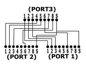
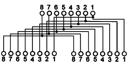
The diagram sticker on the actual victron splitter available on their products page depicts generic splitter wiring, but is there another reason it would work where a generic RJ-45 splitter doesn’t?