Hello! I’m using a MultiPlus 24/3000/70 in my expedition truck. During summer, my 1,2 kw solar system delivers more than enough energy but during winter the solar yield is limided. I recognized that the self consumption of the MultiPlus - that is running all the time - is significant. Since I have some 230 AC devices that need energy supply permanently, I was wondering if it is possible to add a little victron inverter (like the inverter 24/250) to the system. I would like to integrate the little inverter in a way that it is always running assuming that the self consumption of such a little device is much less that the self consumption of the Multiplus 24/3000/70. The MultiPlus should stay in a sleep mode and only in case the consumption exceeds 250 VA or my vehicle is connected to shore power for charging the MultiPlus should turn on atomatically. Is it possible to combine two devices in such a way and where do I find information how to set up the system properly. Thank you so much for your support!
Running them in parallel or as part of the same communication or GX system is not possible. However, you could use a small Phoenix like a DC load.
Connect whatever load needs to run permanently to the Phoenix, let this switched on all the time. No communications to the rest of the system. You could use a smartShunt set as DC monitor if you want to know the consumption in the main GX system (if equipped)
Use the Multiplus either switched off or in search/AES mode. Whenever shore power is available it will switch trough and also charge the batteries.
It would be two separated 230V supplies however. Yes you could use ACout2 to do some switching over, but imho not worth the trouble
Okay, that really suprises me. I think this is a very common situation I have and I have expected that there is a solution for it. If I get you right, the only way is to install two seperate 230 VAC supplie systems - one for consumers with little consumtion that have to be always on and another for consumers with high consuption with the MultiPlus in search mode. This is exactly what I want to prevent. I want to have one 230 VAC supply system wich is fed by a little inverter permanently that is supportet by a the bigger MultiPlus only in case the total consumption exceeds the capacity of the little inverter.
However, if there is really no way to relize such a setup I wonder if I’m mybe wrong with my assumtion that such a set up would significantly reduce the system’s self consumption?
The trouble is, if you have 2 independent inverters on one ac system they have no way of synchronising the ac waveform, so one inverter could have the live at +230V whilst the other has its live at -230V. Something is going to go bang. You can not get the 2 inverters to synchronise.
The second optikn suggested also has to be approched with caution. Because the larhe and small inverters can be out of phase, you can potrntially get 400V ac difference between the 2 systems. You need to make sure that they are seperated.
If you have constant small loads, then using them directly on DC is the best solution. Theres DC/DC regulators out there for all voltages, even for the funny Sony device that needs 7.8VDC
I have a very similar situation. My domestic 24v DC adapted fridge died in France and the fridge engineers won’t now touch domestic R134a, and on a boat. (although the garages still service vehicle R134a). I could take it back to the supplier in UK, but don’t have the time etc. My essential systems are DC - freezer, water pump, sump pump, WC, satellite receiver.
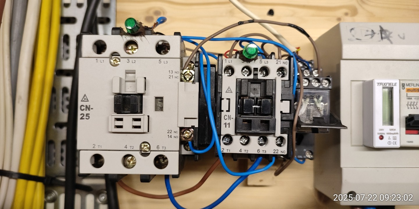
The Frigoboat/Vitrifrigo are €€€€. So I’ve gone 240v Liebherr and currently a dedicated 24/500. I too would like to use the 500 for a few light loads., leaving a MP 3000/24/70 for larger loads. The only way I’ve worked out is to use a pair of interlocked contactors, so when the MP is switched on the 24/500 is switched off first. My box of build leftovers had all the bits required.
The only issue is of course coil current consumption.
I have yet to finish the wiring.
I would have thought Victron could do this - as with interlinking MPs.
You could use an automatic transfer switch, then you don’t have the coil consumption of relays.
Any links to an ATS and price?? A quick google and ATS seem to use contactors = coils and at least £250 in UK.
Not convinced that a 16A+ capable ATS won’t be a couple of contactors in a smart box.
Even using power relays will involve coils.
Could a series connection of a second Multiplus (e.g. 24/500) at the AC_Out of the big MP 24/3000 work? This could be detected as a generator, the Multiplus can synchronise to the AC wave and the standby power consumption is about 6W.
Victron sells them and you can also find them on Aliexpress and various other online shops.
Some work with internal relays, others use a pulse coil or small motor to mechanically switch over.
The one with relays are usually faster (typically used in small UPSes) but have the coil consumption.
Those with pulse coil or motor are slower but only consume during the switchover.
This is a (not officially supported) way to provide occasional extra inverting power while keeping self-consumption lower when the extra inverting power isn’t needed, but it won’t work if the Multis are too far apart in power spec.
When you power up a big load, the tiny 24/500 will alarm trip into shutdown long before the big 24/3000 can switch on to take over the load.
A solution like this only works when both Multis are roughly the same power spec.
Thank you. Those ATS units look interesting.
The Victron tech data shows a 6w coil load.
I assume having the 250/500 inverter on the NC contacts and 3000 on NO contacts then there is only coil consumption with the 3000 supplying.
The 10s relay I guess is for the generator to get up to speed before the load is transferred. So with 2 inverters is probably not required.
Just an NC auxiliary contact/simple relay to switch off the 250/500 using the remote switch.
I’ve looked at some of the Aliexpress items and “infrequent switching” is a common requirement - but that might be translation. So whether they would cope with much more than that, I don’t know.
Some more research.
This one looks interesting:
https://www.aliexpress.com/item/1005009266034774.html?
I haven’t found any coil/consumption details.
Just take caution with the ones from Ali.
One of the teardowns here .
This gives an answer for “infrequent switching”. Some of the cheap ones have the ventilation openings with contacts visible - bad for places where dust or moisture is possible as well as not funny when contacts will sparkle during switchover (and they will).
I’d stick with the purely mechanical ones, unless you’re planning on a lot of switchovers.
In that case I’d look at either a proper ATS, or at rewiring my consumers so that the critical low power ones have a feed from the smaller Multi and the larger noncritical ones have a feed from the big Multi.
I watched the video in the link in post by JanisD. Useful.
And got the 1 phase Automatic Transfer Switch that is referred to towards the end, instead of the Transfee. Much beefier inside.
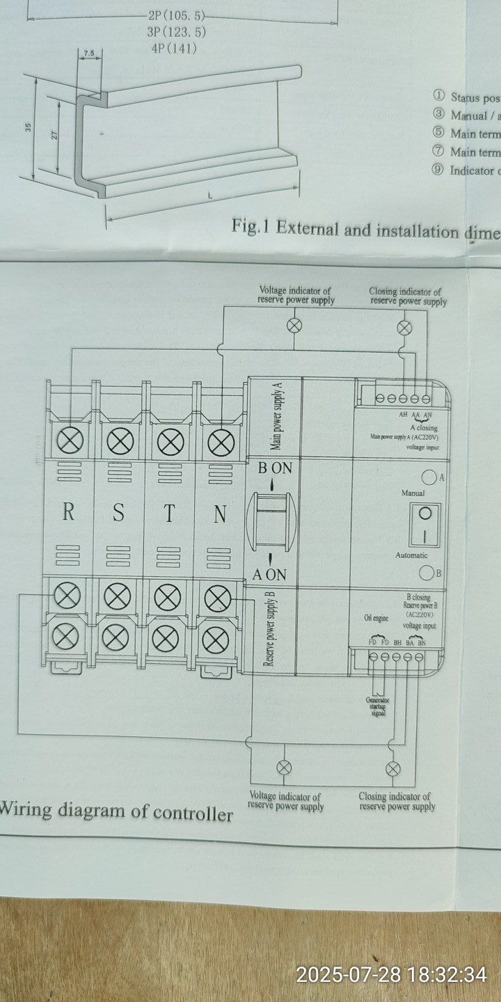
I can’t fathom out the 1 and 2 passive signal outputs in the diagram. I was hoping to find 2 sets of Com, NO and NC contacts. And use them to switch off the 500VA inverter when the 3000 is switched on.
There is a 3 pole dual throw relay in the box.
And the Reserve side has two contacts marked “Generator Startup Signal”.
But there doesn’t seem to be any continuity to start a generator when the main power supply goes off.
I could use an external relay.
So, slightly perplexed.


I might be wrong (not familiar with this specific ATS, but they are all pretty much the same) but I doubt very much that this ATS has a “generator start” contact - that’s usually done by a generator controller.
None of mine have such a contact, they just have a contact signalling which input is active.
The “generator startup” contact you see in the drawing (but not on the unit) seems to be some kind of “generator is running” detection contact, as there is “Oil engine” written above it.
So my suspicion is that this is supposed to be wired to an oil pressure switch on the generator, to prevent running load on the generator if it isn’t providing proper oil pressure or so ?
I wouldn’t connect that contact to anything until I’ve properly measured what it actually does.
How I would program & wire such a thing:
- connect the 3000VA Multi to the “Grid” side, so it takes preference if present
- connect 500VA Multi to the “Generator” side
- Program an assistant in the 500VA that turns the programmable relay On if Load is higher than 420W for 1 second
- Program an assistant in the 500VA that turns the programmable relay On if Load is higher than 400W for 15 seconds
- Program an assistant in the 500VA that turns the programmable relay Off if Load is lower than 250W for 60 seconds
(loads and timings might need to tweaking) - Wire the relay of the 500VA Multi to the “Remote” input of the 3000VA Multi
I’d also wire in an override switch on that input so you can force the 3000VA Multi to be On.
Thanks. The 500VA doesn’t have any form of programmable assistant.
So, I’ll have the 500 remote wired through a relay NC. And coil wired to 3000VA. So when the 3000 is switched on, it will switch off the 500VA.
I can’t find any ATS terminals that equate to change over contacts.
You sure about that ?
What firmware version is it running ?
I’ve specifically looked up the datasheet to be sure that the Multiplus 500VA has a programmable relay.
Yes. It is not a Multiplus - it is one of these - Inverter VE.Direct | Victron Energy
Simple box.