question

Johan Pool avatar image
Johan Pool asked

3-Phase Multiplus II GX ESS - Feed-in not controlled

Hi Everyone,

I have logged two other questions on the same issue and has not resolved the issue. I am again asking the question should someone has seen this before. Currently the local wholesaler and Victron is attending to the issue, but are not making progress.

https://community.victronenergy.com/questions/77312/3-ph-multiplus-2-erratic-behaviour.html

https://community.victronenergy.com/questions/79818/ess-3-phase-system-feeding-back-to-grid.html

The above is more for background as I will attempt to continue to describe my thoughts below which might help or not.

The three pictures below show some details on the respective phases. As explained previously the issue is most prevalent on L1, less on L2 and absent on L3. I have moved inverters between the phases and the issue remains on L1 thus it doesn't seem to be inverter hardware related. Could still be software or coding, they have however all been upgraded to the latest version.

The wholesaler has also reconfigured the system from a software perspective and the issue remained.

I will start below with L3, which I believe is working correctly:

solar-l3.png


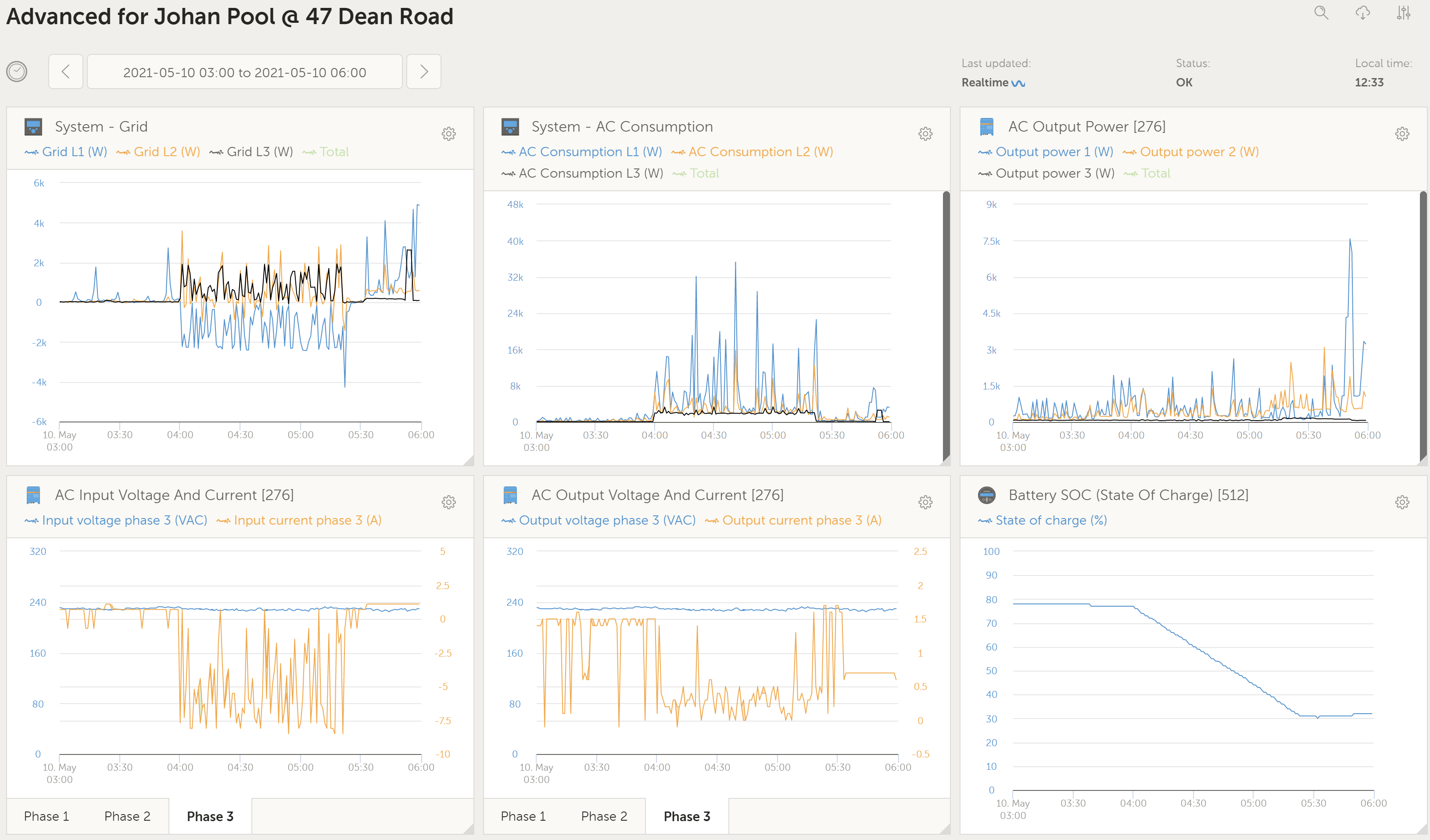
As can be seen on the System - Grid graph the L3 line stays above feed-in to the grid and the average current on the AC Input Voltage and Currrent - Phase 3 graph is around -8A. The load on this phase at the time is approximately 1.8kW and although quite noisy is relative consistent when looking and the calculated non-critical load side throughout the period that the element is on.

On the opposite side the L1 phase reacts completely different as per below:

solar-l1.png

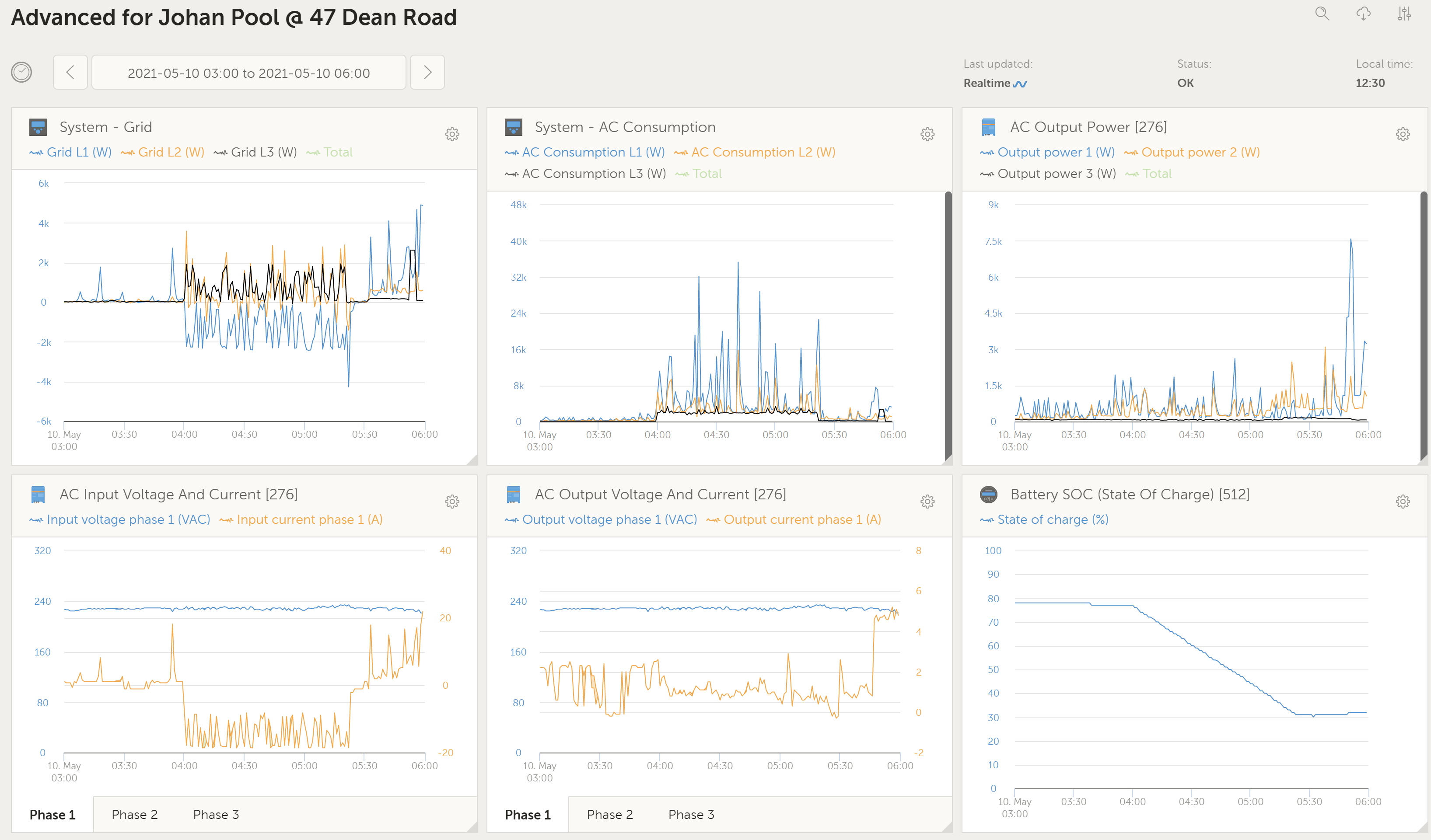
During the same period, you can now see that L1 pushes power back onto the grid. The AC Consumption calculation becomes very erratic at this stage and seemingly due to the system trying to calculate the additional load on this phase and significantly overshoot. The AC Input current averages at approximately -16A during the period which is double what is seen on the other two phases.


During this period on the remote console the system seems to jump as can be seen on the peaks of the AC consumption and then slowly regulate back to the required power and seemingly jump again as soon as it gets back to the correct power. IT seems that there is a calculation error as soon as it gets back to balance that makes the inverter over-react to try and accommodate these calculated excessive loads. This then just push back onto the grid until it can then correct itself over a few minutes.


Any help, suggestions or requests for more information would be appreciated and accommodated. At this stage we are not making progress with the local support and it seems their next option would be to strip out the whole system to take back to their office to test.

ESS
solar-l3.png (434.2 KiB)
solar-l1.png (432.2 KiB)
2 |3000

Up to 8 attachments (including images) can be used with a maximum of 190.8 MiB each and 286.6 MiB total.

2 Answers
Johan Pool avatar image
Johan Pool answered ·

Morning,

I am ecstatic to report that I have found the issue and resolved it. A basic, probably amateur mistake, but glad it is resolved. Will have to see how I redeploy the inverters in future or Victron maybe one day evaluate their software to utilise the functionality. Although mentioned in my historical posts it didn't possibly come out that clearly and thus why I didn't have success in getting someone to assist me in resolving it.

My system has 3 x Multiplus II GX units, as well as a Cerbo GX that does the control. With multiple GX units in the system although I believed only the one would be controlling as a master and the other would be dormant, the others within the Multi's did something on the network to create issues. I have unplugged the VE.Bus cables on the Multi's GX units last night and everything returned to normality. System control is much better and I will monitor for a few days.

I would however need to decide whether I completely disconnect the GX module. Currently the displays read System off, which would most probably burn in. I would in future relocate the units to other installations and replace with non-GX inverters. Some money wasted during the installation and would have hoped the installer would have been knowledgeable enough to not make such a mistake. Well some school fees paid.

Kind Regards

Johan Pool


2 |3000

Up to 8 attachments (including images) can be used with a maximum of 190.8 MiB each and 286.6 MiB total.

markus avatar image
markus answered ·

Hi Johan,

I am trying to understand your issue.

As far as I got it by now, your overall consumption calculation is way off on L1 and L2, when you feed non essential loads on AC-In side of your system?

Can you please include the VE.Bus AC Input power to your VRM graphs? This is the side of the Multis that covers your non essential loads. Not only AC-Output, this covers only the essential loads.

But as a quick first guess, this sounds like the phases on the Grid Meter are not wired to the corresponding Multis. Pls. double check that the wire connected to your EM24 on L1 is going to your L1 Multi, EM24 L2 -> Multi L2, EM24 L3 to Multi L3.

And pls. double check that you are running latest Firmware on your Multis, CerboGX and MPPTs; say all your devices. ;o)

It would also help much, if you could draw a quick schematic of your installation, so we can follow easier.

Best Regards,

Markus


2 comments
2 |3000

Up to 8 attachments (including images) can be used with a maximum of 190.8 MiB each and 286.6 MiB total.

Johan Pool avatar image Johan Pool commented ·

Hi Markus,

Thanks for the comments. From a firmware perspective it is all the latest, checked by myself as well as the wholesaler.

We have traced the CT to phase connections a number of times, when I do swap them around (CT's from L1 and L2) the inverters start running away as expected as it is not getting the expected response.


Below a quick schematic of the system. Please let me know would you need more details on any of the components.schematic.png


Below is a graph for the AC-Input power for the same period as the original graphs. As you can see the spikes you see on this graphs are massive, and not seen on the voltage and current graphs for the AC Input as per above. Again illustrating why I believe it is a calculation issue in the Cerbo GX that causes the issues.


ac-input-power.png


Thanks again for the assistance. Looking forward to your comments.

0 Likes 0 ·
markus avatar image markus ♦♦ Johan Pool commented ·

Hi Johan,

You have the CT version of the EM24.

Did you make sure the CT ratio is set correctly in the EM24 menu?


I would start to diagnose like that:

.) switch off all loads and consumers

.) switch off your Multis

.) take a bigger defined load maybe some 2kW heater

.) connect that heater to each of the phases on AC-IN and compare the power values that the EM24 sends to the GX, to be legit and on the right corresponding phase. Loads should be displayed by a positive number.

.) if that values are comprehensible, switch on your Multis again and send the ESS system to "passthru", by disconnecting the EM24 from the system (disconnect RS485 USB dongle from the GX).

.) repeat the tests with that heater on AC-Out phases one by one and compare VE.Bus AC-In and AC-Out Power, as well as Voltage and Current. Check if the values are legit and phase order is correct.


Please come back with the results.

Those tipps above mean measuring live AC circuits. If you have any doubts or are not allowed to do this by yourself by law, please consult a local electrician to do those tests for you.


I wish you success.


BR


0 Likes 0 ·