question

flyerndiver avatar image
flyerndiver asked

100|30 doesn't like my six panels -- okay with four.

img-20201016-161148-hdr.jpg screenshot-20201031-145041.jpg
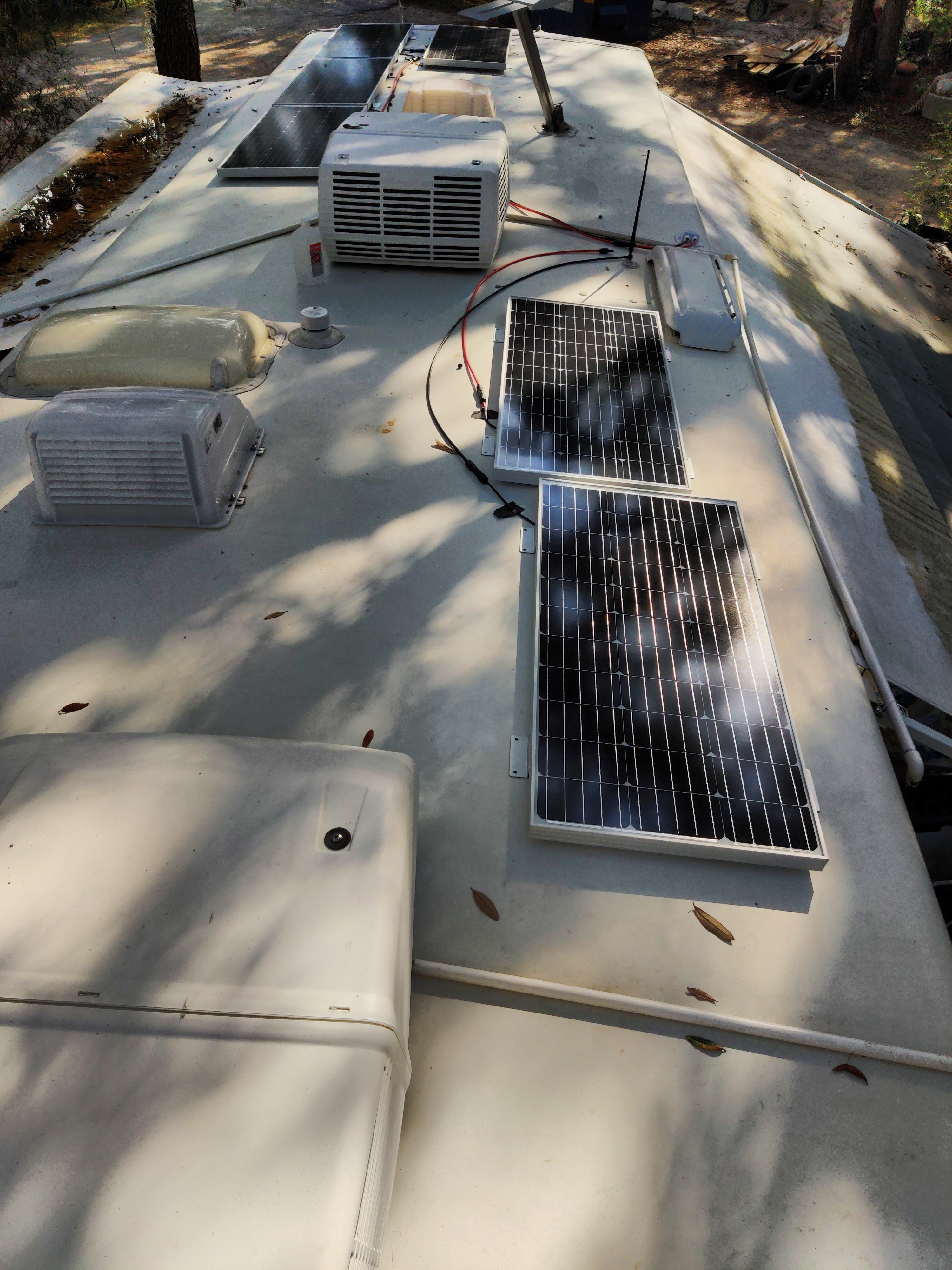
I installed four 100 watt panels flat on the curved roof of my RV in two series strings paralleled. About a month later, I added two more 100 watt panels in series and paralleled them with the existing strings.
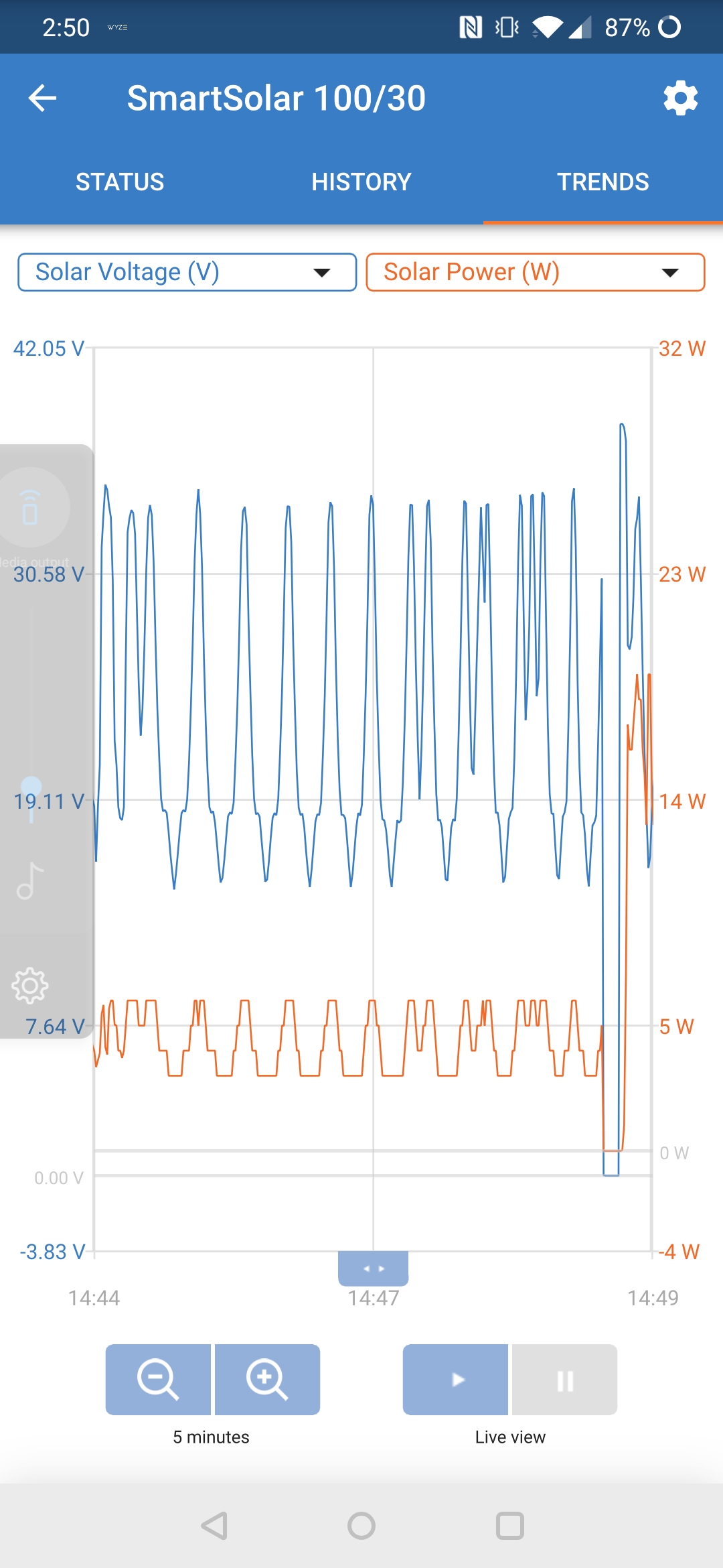
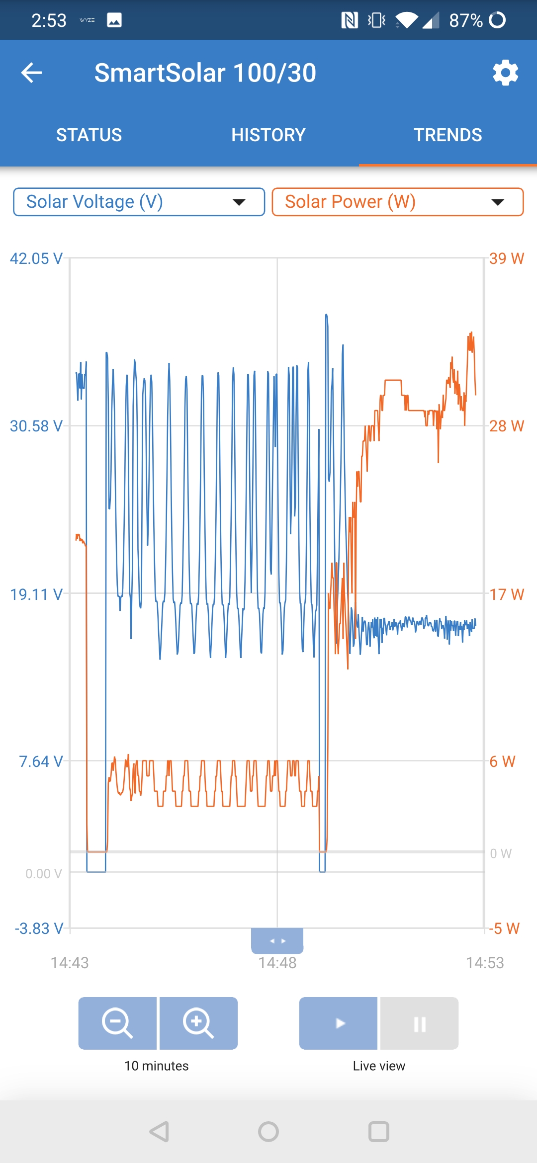
All are Renogy 100 watt compact size mono. The minute that I powered the system back up after ADDING two more panels the output DROPPED to about 20% of what it was with only four panels. All of the panels pass open circuit vo screenshot-20201031-145308.jpgltage and amperage tests themselves and for each of the three series strings.
I added blocking diodes thinking that maybe the panels in shade at the time were consuming power somehow. That didn't do anything of consequence.

I moved the RV into full sun and tried a bunch of different configurations of this string with that string, and no matter what, when all three strings are paralleled, the output is crap. I swapped around the branch connectors, resistance tested my cables, rechecked each panel and each string for OC voltage and amperage, switched cables around, tried every combination and permutation I could think of. And no matter what, the controller refuses to produce when all three strings of two series panels are connected. I can combine any two strings with any cables, and any combination of branch connectors, and get acceptable and expected output for the way they're mounted.

The controller is a Victron 100|30 Smart. Feeding four Trojan T-105's.

Now before you say 'that's too much; you're going to fry your controller', please take a look at how they are installed and note the curvature of the roof. I over-paneled for a reason. It is impossible for any single panel to get full sun at anything less than a 30 degree angle of incidence, let alone all of them at once. Furthermore, the way I use my RV frequently has it well shaded. The highest efficiency I have seen yet with the four panels is about 50%. My calculations lead me to believe this is well within the controller's tolerances. Am I wrong in this thinking?

Are the lengths of the cables being unequal somehow an issue; are these controllers so sensitive that milliohms matter? Is there some other electrical phenomenon that I've fallen prey to? I've included a few screenshots of the controller's behavior. When all three strings are connected, it seems to exhibit a seeking behavior, but never makes up it's mind. What that I am missing here?

I've previously queried a FB group with substantially the same questions and received many suggestions for things to check which I had already done multiple times. The emerging consensus there was that I need to buy another controller. I'm being told that I can't parallel three strings into one controller. Is that the case? That makes no sense to me. Would four strings work? Could something downstream cause this?

I think the biggest clue is the 'hunting' behavior of the controller, but I'm beyond stumped and pulling my hair out. HELP! And if you're in the Tampa area, I'll buy you a beer or two...

Thanks so much for any and all enlightenment!
MPPT SmartSolar
6 comments
2 |3000

Up to 8 attachments (including images) can be used with a maximum of 190.8 MiB each and 286.6 MiB total.

Hi @flyerNdiver

Can you please post a system wiring diagram?

Looks like a bad connection to me, that won't necessarily show up as resistance until there is current flowing. Have you done short circuit current testing of the PV cables at the MPPT point of connection? Be careful of course, and make sure the test equipment is suitably configured and rated. You should do this on individual pairs of series connected panels. NOT while they are connected in parallel (as that is almost surely over 10A, and above the rating of most multimeters).

Also panels are nearly useless in the type of shade shown in your picture, so any testing must be done in full sun. I know you mentioned this, but important to remember, and stay in the full sun as long as you are testing. Also make sure your battery voltage is low/not full so that is not a limitation.

0 Likes 0 ·
flyerndiver avatar image flyerndiver Guy Stewart (Victron Community Manager) ♦♦ commented ·

I am not an artist. I did this between clients in a few minutes. It should be serviceable for intended purposes.

rv_wiring_solar.pdf

0 Likes 0 ·
rv-wiring-solar.pdf (433.5 KiB)
Paul B avatar image Paul B flyerndiver commented ·

were you have added the extra 2 panels check that you have the pos and neg the correct way around. measure with a meter done presume that the colors are correct.

also some status page screen shots as well from the solar reg please

0 Likes 0 ·
flyerndiver avatar image flyerndiver Paul B commented ·

I have checked the polarity probably ten times -- maybe I'll do that again.

There are some screen shots up top. What do you mean by "solar reg?"

0 Likes 0 ·
Guy Stewart (Victron Community Manager) avatar image Guy Stewart (Victron Community Manager) ♦♦ flyerndiver commented ·

I don’t see any mention of what the PD converter is that you have attached the MPPT too.

Can you try bypassing that and connecting the battery connection of the MPPT directly to the battery terminals while the battery is low voltage/not fully charged and the panels are in full sun.

Some more photos of the installation, especially of all the connections would be useful.

0 Likes 0 ·
flyerndiver avatar image flyerndiver Guy Stewart (Victron Community Manager) ♦♦ commented ·

There are two terminals for each polarity on said converter. I used it as a handy and convenient buss bar; I think we could be on to something here. For the record, the converter is always unplugged during testing. It's two connections are merely a convenient point to tie in and my calculations tell me that the 8 AWG wire coming out of it are sufficient to carry the max current of either the MPPT or the converter, but not both at the same time.

I have some 2 AWG wire (2 paralleled 4 AWG) that came with the renogy inverter (not converter; not a typo). The inverter is close by. Is there any reason that I cannot use some of that and tie in to the 2/0 wire that feeds the inverter? The 2/0 is fused at 300 amps, (BSS block fuse) but other than that runs directly to the battery bank, it's new and done right and would bypass all of the existing RV stuff.

0 Likes 0 ·
2 Answers
Paul B avatar image
Paul B answered ·

I don't think its a MPPT charger issue, Try connecting 3 panels in series and the other 3 in series then connect the two strings in parallel (IMPORTANT MAKE SURE PV Open circuit voltage does not exceed 100 volts) even though you have 600 watts in theory available. you cant overload the controller as it will ONLY give a MAX of 30 AMPS OUT. only way to overload this unit is to put TO HIGH A PV open circuit voltage ie over 100 volts open circuit.

OR for testing try connecting each pair of 2 strings to the charger and look at the voltages and report on each strings voltages in preference do this when all panels have the same sun load.

Please send screen shots of each string of 2 panels when connected. we want PV voltage PV amps and DC voltage and DC amps for each pair of panels.


2 |3000

Up to 8 attachments (including images) can be used with a maximum of 190.8 MiB each and 286.6 MiB total.

michelg avatar image
michelg answered ·

Hi Flyerndiver ! I will suggest you to open the boxes in the back of your panels, and check IF the weldings are fine or not, if the diodes are also welded or not, or if any / several diodes are damaged. That could be an option, also, if they are correctly installed by the PV panels maker.

It happened to me, a diode was DOA, and some connections were not welded.

Michel

2 |3000

Up to 8 attachments (including images) can be used with a maximum of 190.8 MiB each and 286.6 MiB total.