Hi Victron team,
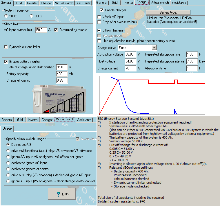
I have configured an ESS parallel system based on the following components: CCGX running on Raspberry PI (v2.20), MultiPlus 48/5000, BlueSolar MPPT 150/35, PV inverter on AC IN and CAN REC-BMS controlling charging/discharging of 400ah 16s Sinopoly LFP battery.
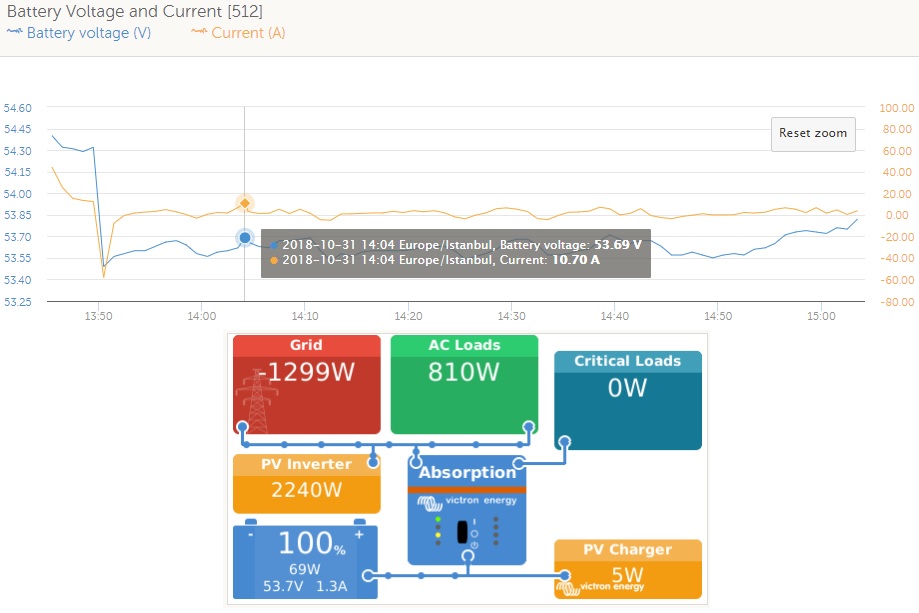
When the battery reaches 100% SOC the Multi switches to inverter at full power and starts discharging the battery into the loads/grid. Also, even the MPPT is ESS/CAN controlled it continues to supply current into battery at 100% SOC.
Please see the attached pictures. In pictures number 1 and 2 you can see the battery at 100% SOC as is reported by the BMS and the charging parameters. The max charging voltage is correctly lowered and displayed at 52.8V. At any SOC below full this parameter is 55.2V
In picture number 3 you can see the MPPT parameters. Why is the charge voltage 60.8V? This value shouldn't be controlled by the BMS?
In picture number 4 you can see how Multi discharge the battery right after this reaches 100% SOC
Finally, in picture number 5 you can see how MPPT continues to charge the battery in battery hysteresis period (max charge voltage still at 55.2V)
Thanks,
Mihai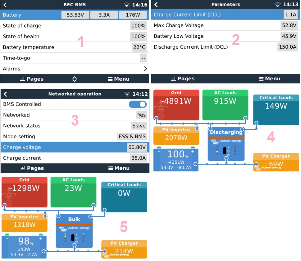
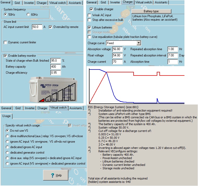
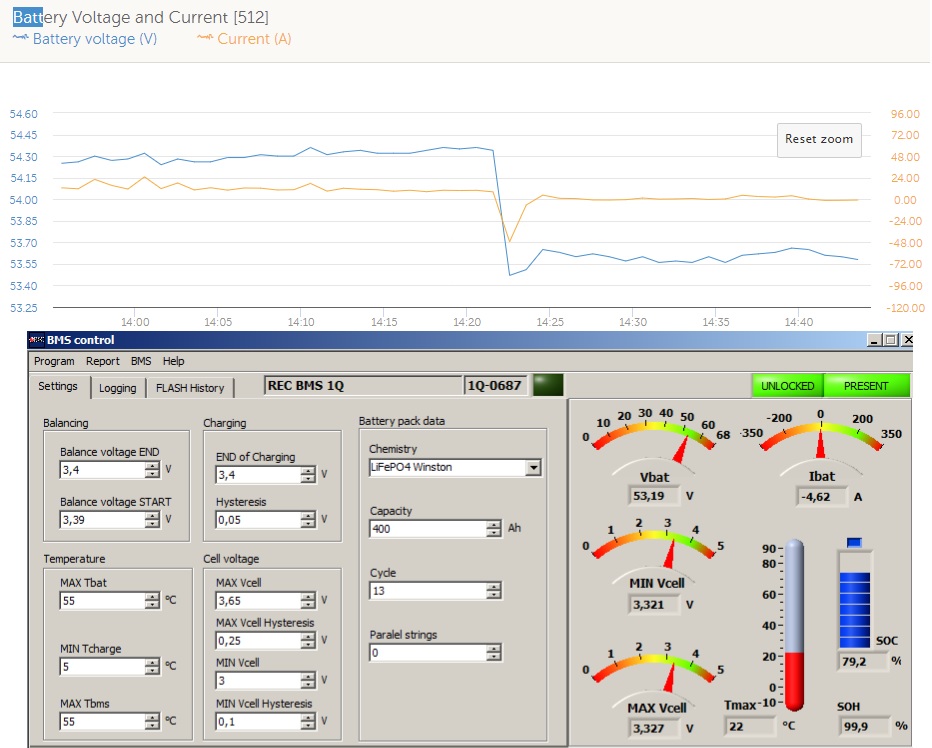 Problem solved. Setting the end of charge voltage hysteresis at 0,05V solved the problem.
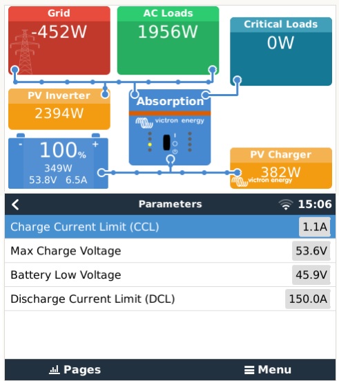