question

perma-batteries avatar image
perma-batteries asked

ESS parallel topology clarification

Hello fellow installers,


We're about to set up a DC coupled ESS comprised of a Multi 5 kVA and a MPPT 250/100. So far we've been wiring ESS with an in-line topology, which is pretty straightforward, but in parallel, we got confused by the external CT and the relevance of using the AC-OUT 2. We couldn't find neither any specific wiring schematics detailing the various possible configurations when using a parallel topology. Feed-in is not tolerated, and we need to proceed with parallel wiring of the system, as the subscribed grid power of the customer is at 65A (~ 15 kVA), higher than the internal relay of the Multi. The wiring diagram would looks like this :


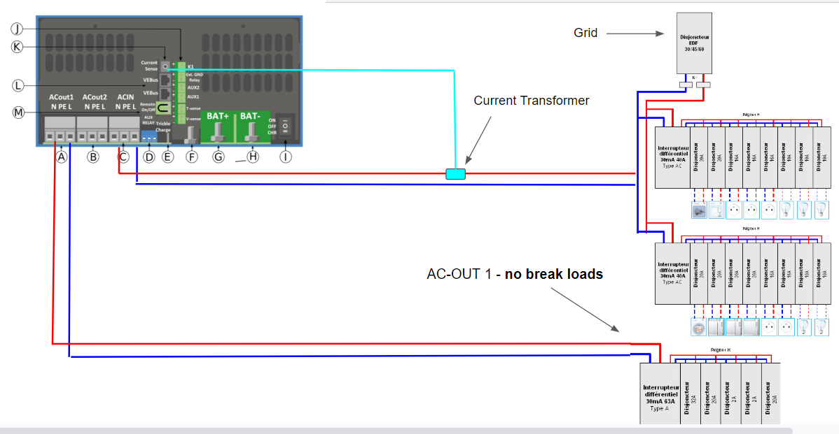
Some remarks, for which we'd like to have confirmation from installer who have already installed ESS in parallel mode :


- First, the CT should be installed downstream, before the main switchboard, so that it can monitor the power drawed from the grid and thus prevent feed-in and matches the grid setpoint set in the GX, correct ? Problem is that it is rated for 32A max, if the loads draws more than that, the monitoring will not be precise and we need to use instead a ET112 @100A, correct ?


- Second, in normal operation, as the AC-IN line is bi-directionnal, all the switchboard will be energized both by the PV power from the DC bus from the Multi, AND the grid if needed right ? If the grid fails, only loads connected to ACOUT1 are still powered, correct ?


- In parallel topology, how we can use the AC-OUT 2 ? As all non critical loads are powered by AC-IN, what's the usefulness of having an AC OUT 2 which has no backup and which is limited to 32A ?


Thanks a lot folks !


ESS
1572537738278.png (201.8 KiB)
2 |3000

Up to 8 attachments (including images) can be used with a maximum of 190.8 MiB each and 286.6 MiB total.

1 Answer
Guy Stewart (Victron Community Manager) avatar image
Guy Stewart (Victron Community Manager) answered ·

Hi @perma-batteries,

From the Diagram, please check the placement of the grid meter/CT. It should be positioned so that it is the first/last thing before the grid, and all current must flow through it.

1 - You are correct the CT is too small, and you will need the higher current ET112 connected to the GX device.

2 - Correct, the Multi will remain connected and push power out the AC input, until the grid drops out, its Loss Of Mains detection kicks in, and the AC input relays of the multi's are opened. Loads connected to ACout will still be powered.

3 - Use of AC-out2 can be reprogrammed as you like with the use of VEConfigure assistants.

You could have low-priority loads attached, for example an outbuilding circuit to a shed, that is only available while the battery is above 50% of usable capacity, or AC-input is connected. Then if the grid drops out, and the battery is half flat, the AC2out relay opens and leaves the last 50% of battery capacity for the ESSENTIAL loads that are connected to AC1out.

Or not use it at all.

1 comment
2 |3000

Up to 8 attachments (including images) can be used with a maximum of 190.8 MiB each and 286.6 MiB total.

perma-batteries avatar image perma-batteries commented ·

Hi Guy, thanks a lot for your precise answers !

0 Likes 0 ·