question

andyc247 avatar image
andyc247 asked

Energy Monitoring on UK ESS System using Henley Blocks

I am considering adding a MultiPlus in parallel with my existing grid tie PV system. My installation is in the UK where the cables from the electricity company meter go first to two Henley Blocks for live and neutral. One set of tails from the Henley Blocks go to the house consumer unit and another set of tails from the Henley Blocks go to the solar consumer unit and from there to the PV system via the Solar Generation Meter. This is a fairly normal UK arrangement.

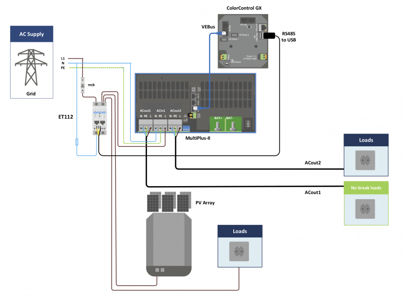
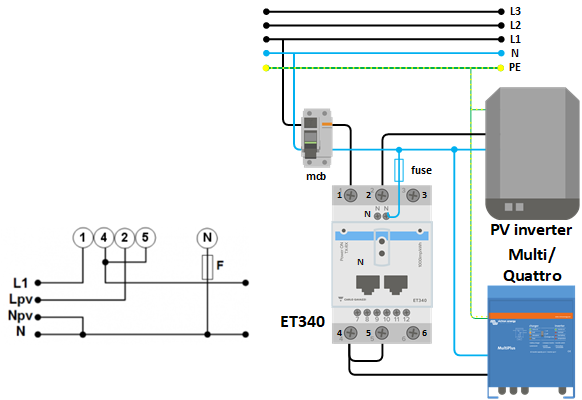
Since the house loads are on the AC-In side of the MultiPlus, for an ESS system I believe I need a Victron Energy Meter connected to the CCGX. If I use an ET112 in my installation I think the ET112 would need to be installed between the Henley Blocks and the electricity meter together with an isolation switch in order to measure net flow to/from the grid? But it also looks like I could use an ET340 in its dual function arrangement. The example wiring for this looks like I don't need to have new cabling between the Henley Blocks and the electricity meter. However I don't understand how this dual function arrangement can calculate the net grid flow since it doesn't measure the house loads? For example, let's say the house consumer unit loads are 2KW and the solar PV is generating 1KW so 1KW is pulled from the grid. With the ET340 in dual function arrangement, how is the MultiPlus instructed to supply 1KW from the storage battery (if there is enough energy in the battery) to end up with a net zero watts from the grid? I would very much appreciate an explanation for my example as I am currently missing something somewhere!

Hope the above makes some sense!

Many thanks,
Andrew


ESS
2 |3000

Up to 8 attachments (including images) can be used with a maximum of 190.8 MiB each and 286.6 MiB total.

3 Answers
wkirby avatar image
wkirby answered ·

The system grid meter needs to be able to measure the current of the loads with the MultiPlus' AC-IN being regarded asone of these loads. This way, the MultiPlus can backfeed to compensate for the loads by actively attempting to make the grid meter read 0W (or whatever value the grid offset is set to).

The PV meter on AC-IN needs to be on one of the load ciecuits down stream of the grid meter, before the MultiPlus. This is so that the MultiPlus can impose as much load as necessary to charge the battey ffrom AC-IN whilst maintaining 0W on the grid meter. In this condition battery charging and house loads are satisfied by AC coupled PV with out feeding in until the batery fills up then the grid meter will go negative power (backfeed).

Basically the meters cannot be on a circuit (or pair of meter tails) the the MultiPlus cannot influence by load or backfeed energy.

2 |3000

Up to 8 attachments (including images) can be used with a maximum of 190.8 MiB each and 286.6 MiB total.

sean avatar image
sean answered ·

For UK 1Ph grid parallel installs, I simply fit the ET112 inline with a single meter tail - you'll obviously require an isolator or be suitably qualified to pull the DNO fuse to do this.

I question the accuracy, by the apparent omission of a means to meter total grid demand/direction of the dual function documentation relating to the use of the 3ph meter within a 1ph ESS. The neutral connection to the meter is low current, the fuse is typically 1A, the MCB is omitted as depicted, ACin1 simply feeds a suitably sized MCB in the consumer unit.

The below schematic is accurate, and will enable grid zero and balance, but it's an over simplification for a typical UK grid parallel installation (ACin1)


2 |3000

Up to 8 attachments (including images) can be used with a maximum of 190.8 MiB each and 286.6 MiB total.

andyc247 avatar image
andyc247 answered ·

Thanks for the replies. I think the diagram for the ET340 in dual function mode is confusing because it does not make clear where the house loads connect:


I can now see that the house loads need to be connected to 4 / 5 on the ET340 in parallel with the Multi / Quattro and then it makes sense. If I am correct then I think the above diagram needs better labeling to make it clear where the house loads connect to.

Thanks,

Andrew


1572005379069.png (59.6 KiB)
1 comment
2 |3000

Up to 8 attachments (including images) can be used with a maximum of 190.8 MiB each and 286.6 MiB total.

sean avatar image sean commented ·

The RH schematic appears to be an illustration of using the 3ph meter, to meter a 1ph installation on just one of the phases of a 3ph supply.

The LH schematic is illustrating how to meter both PV and grid, using the 3ph meter, on a single phase installation - the house loads feeding from 4/5.


0 Likes 0 ·