question

kodiak avatar image
kodiak asked

Nominal PV power, 36 V

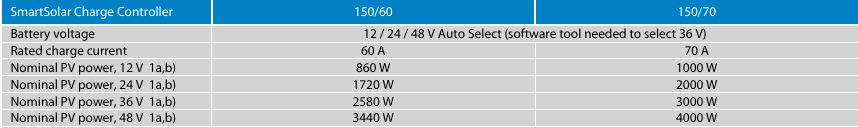
I am trying to size my MPPT solar charger to my PV and I need a bit of clarification on the specs listed on the Victron solar charger I want to purchase (Smart Solar 150-60).

When the specs say "Nominal PV power at 36 V can handle 2580 watts", am I correct in understanding this means that if the voltage from my panels coming into the MPPT is 36v, then it can handle up to 2580 watts worth of panels?

I know that I also need to keep my volts and amps below the MPPT's rating. My system will be supplying 36v, 33 amp to the MPPT.

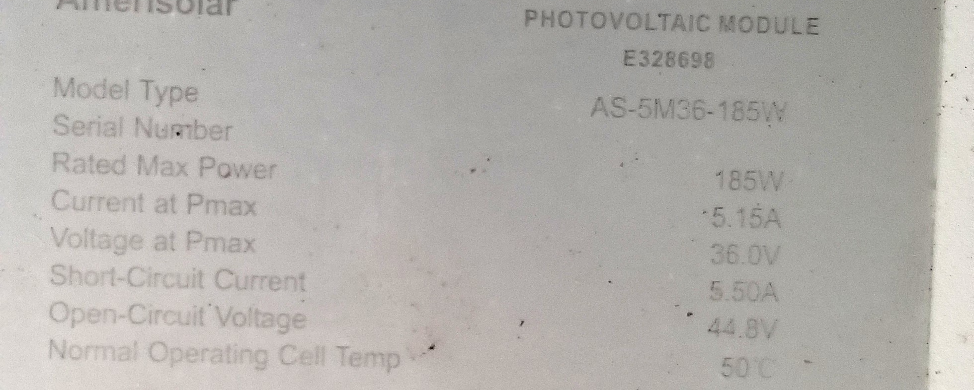
I plan on running 6 x 185W panels in parallel. Each panel is 36V and 5.15 Amp.

Thank you.

MPPT SmartSolar
2 |3000

Up to 8 attachments (including images) can be used with a maximum of 190.8 MiB each and 286.6 MiB total.

6 Answers
snoobler avatar image
snoobler answered ·

It's referring to battery voltage, not panel voltage.

MPPT 150/60 means:

150Voc maximum PV voltage in all instances (allow for cold temp effects)

60A output to battery, so max power depends on your battery voltage.

Victron MPPT are over-paneling tolerant. As long as you don't exceed 150Voc or the PV input current limit with array Isc (50A max on that unit), you're good.

Lastly, your array Vmp should be at least 1.5X nominal battery nominal voltage to ensure adequate voltage for charging.

2 |3000

Up to 8 attachments (including images) can be used with a maximum of 190.8 MiB each and 286.6 MiB total.

ykdave avatar image
ykdave answered ·

Those ratings are for 12/24/36/48v charging voltages. The 150/60 can handle an array up to 150v and charge rates up to 60a


Oops. Snoobler beat me to it!


If you’re running a 12v battery bank you will not be able to realize the full potential of your array under perfect conditions

1 comment
2 |3000

Up to 8 attachments (including images) can be used with a maximum of 190.8 MiB each and 286.6 MiB total.

kodiak avatar image kodiak commented ·

If I understand you correctly, the "PV power 12v" is referring to the voltage of my battery packs, not what the PV array is producing.

If this is the case the 150/60 will only handle a 860 W array. To better achieve all of my PV potential, I would be better off using the 150/70 because it will allow for a 1000W array (Still not enough for all my panels)

1716505192021.png

I hope I am understanding this correctly, and thanks again for your help.

0 Likes 0 ·
1716505192021.png (24.3 KiB)
Alistair Warburton avatar image
Alistair Warburton answered ·

"Each panel is 36V and 5.15 Amp" Well that may be part of it, but it isn't the whole story and you need to be considering other factors...

Which Is I guess why you are asking, so treat that comment as an opening as opposed to a criticism, because that is how it is meant.

A PV panel is essentially a DC supply with a relatively high impedance. They are almost always specked at 3 important conditions...

Open circuit voltage...

This is what you will see if there is no current, for example when the battery is full or the grid is off, shutting down the PV charger/inverter, and there is even a modest amount of light.

Short circuit current...

All but self explanatory, the current you will see in optimal conditions with no load impedance, shorted.

Maximum Power Point, MPP or P Max...

The voltage and current at which the maximum power is delivered in optimal conditions.


A typical, 'nominal' 12V panel, in optimal conditions, will have a MPP voltage of circa 18V and an open circuit voltage of circa 21V. The current at any point, open, short or MPP, will of course depend on the panel size/area and will likely be the result of 150-250W / Sqr m depending on where you are, what panels you have and how they are aligned.

NB, Way less in most real world conditions, moderate cloud / light rain, 10% of that; at best!

Assuming your panels are essentially 3 12V cell arrangements in series...

Your OCV will be circa 63V so a string can only be two of those panels or you will exceed the 150V limit of the PV charger when it isn't doing anything, even in relatively low irradiance conditions.

Your system, assuming it has MPPT and is in full sun at exactly the correct elevation, on a cold day, would run at about 54V with all 6 in parallel so about 20.6A overall 1.11kW.

Using 3 strings of two panels in series will double the voltage, without stressing the PV charger in OC conditions, and half the current in your cabling, reducing cable cost and losses. 108V @ 10.3A

Depending on your virtual horizon and assuming ground mount, those same 3 strings, with added back-feed protection diodes could be arranged SE - S - SW with the S facing array at a much higher elevation. The Idea is to have the SE and SW biased arrays grab early and late light with the caveat that one of them is useless at either end of the day. however the low elevation makes the best of early and late light. The S array is then set at a much higher elevation to gibe it a longer window of operating. You are essentially flattening the curve, dial that in and it can be way better than a single orientation.

Have a look at some Solar predictors, Solcast is good, even an API, and free for none commercial use, but there are many to choose from. The important thing is to be able to specify the array characteristics so you can play with a virtual setup and compare options.

Hope that helps. Have fun and give ne a shout if you need specifics.

1 comment
2 |3000

Up to 8 attachments (including images) can be used with a maximum of 190.8 MiB each and 286.6 MiB total.

Alistair Warburton avatar image Alistair Warburton commented ·
Please see below, I neglected to mention temperature compensation, which I should have.

Got corrected and happy to have been.

0 Likes 0 ·
snoobler avatar image
snoobler answered ·

12V system. You'll get about 60A * 14.4V = 864W (or whatever the 12V rated output is).


You have 6 * 185W = 1110W of panels


You propose 6P arrangement with 33A Isc max. You are under the 50A limit on the controller.


130% is not a limit. It's a common recommendation as you won't miss out on that extra 30% most of the time as arrays rarely put out max power.


You are over-paneled (MPPT can't use all of the array power), but well within the allowances on the charge controller (150Voc max, 50A PV Isc max). Given that you are already concerned about shading (shading is typically devastating to PV yield no matter how the panels are arranged, but parallel is typically better), and 5 of these panels are flat on a roof, you will rarely be in a situation where the array will actually produce 1,110W.


I see no issues with the installation. Please be advised that most MC4 connectors are limited to 30A, so how you parallel them is important. You could parallel the 5 on the roof via MC4, but combining the ground panel with the roof array will need to be done in a combiner box. If you combine with MC4, recommend you install ONE 10A MC4 fuse on the (+) lead of each panel.


1 comment
2 |3000

Up to 8 attachments (including images) can be used with a maximum of 190.8 MiB each and 286.6 MiB total.

kodiak avatar image kodiak commented ·
I am looking at using a 6 string combiner with reverse flow diodes in it to negate power syphoning at night or in shaded conditions. Each string will have a 10 amp fuse on it to protect each from shorts or overcharging (which I cant see the later ever happening).

Thank you for your help. It makes some of the decisions I need to make a bit easier.

0 Likes 0 ·
Alistair Warburton avatar image
Alistair Warburton answered ·

I am off grid, I don't use much power, generally, so a huge PV charger just necessary.

I absolutely agree that a huge array on a small charger is not generally a good plan, cost wise, but mobile and off grid is a specific use case.

Providing OCV and ISC are within spec, as stated earlier...

For some, not much, of the year the potential current/power will far exceed what the solar charger can deliver to the battery but the reality is that most of the time irradiance is far below max/optimal and over-paneled, in a conventional sense, is way cheaper than burning fuel in a generator.

The solar charger will just clip, as in, not deliver more than its design max current, and the PV voltage will float up as a result.

I have only ever looked at mine and do not know exactly why an ISC is specked where it is in any given unit.

I believe that ISC is the limiting factor, assuming appropriate string arrangement and thus OCV, when attempting to maximize the energy harvested in low irradiance conditions, and over-paneling to that end.

Are there other reasons no to do it?

2 |3000

Up to 8 attachments (including images) can be used with a maximum of 190.8 MiB each and 286.6 MiB total.

kodiak avatar image
kodiak answered ·

Here are the specs of my panels.solarpanelspecs.jpg

I was hoping to install 6 of them on my RV and run them in parallel. I am hoping this will help reduce the issue of panel shading as much as possible. If I understand things right, the OCV should be no greater than 45v and the Pmax amps will be 31 amps. The battery system I will be running is 2 x Lifepo4 batteries at 12v 300 ah each in parallel.

The PV volts should be high enough for charging these batteries with room to spare and the amps should be less than what the MPPT can handle.

I do have some concerns now, and I am hoping you can help me with them.

  • Do I have too many PV panels for the MPPT to handle, or will it okay considering I will probably never get to optimal conditions. According to the Victron MPPT calculator, their 150/60 Smart Solar MPPT will be at "129% overrated". They say to not exceed 130%.
  • Is running the panels in parallel the best option? I plan on putting 5 on the roof and then one on the ground and move it around during the day to get optimal positioning

Thanks again for everyone's help. I have been researching this project for almost 2 yrs and I have struggled to get any good info that explains things clearly.


1716503526419.png (1.6 MiB)
9 comments
2 |3000

Up to 8 attachments (including images) can be used with a maximum of 190.8 MiB each and 286.6 MiB total.

Justin Cook avatar image Justin Cook ♦♦ commented ·
Nope, you're good. Panel voltage is high enough to keep them in parallel and the combined current of all of them in parallel is still well below the ISC limit of the controller, and you're correct, you'll virtually never see optimal conditions so over-paneling a bit like you are is just fine.
1 Like 1 ·
Alistair Warburton avatar image Alistair Warburton Justin Cook ♦♦ commented ·

Was I wrong, again? My suggestion to use 2 X 3 was based on my understanding, possibly not correct I guess, that the charger was a proper Buck, as oppose to some silly duty cycle PWM throttling. I realize that all in parallel would be fine but reducing the DC current by increasing the DC voltage, within charger spec, and assuming a proper Buck conversion, will reduce losses, due to current, in the cabling.

To be fair I didn't do any calcs to check losses in the cabling against losses in the DC-DC conversion, lack of data mostly, but that was because the DC-DC, being well designed is going to be pretty good, generally, and again generally keeping the MPPT voltage point as high as possible whilst not exceeding the OCV seemed like a good strategy.

If I am fundamentally misunderstanding, or even misunderstanding in Victron specific terms, something here, I would like to know, mainly so I can stop doing it.

Wouldn't 3X2 reduce ISC, due to panel impedance, further protecting the charger MOV's whilst also reducing cable losses, or cost depending on what is installed, and increase buck efficiency?

Don't take this the wrong way I am not suggesting anything you said is incorrect, and I considered all of it when answering, but surly more current = more copper, ergo more cost or more losses if there isn't more copper.. Am I missing something?

I was Trying to be technically correct but answer the unasked, but impotent, or at least relevant, question at the same time.

1 Like 1 ·
kodiak avatar image kodiak Alistair Warburton commented ·

The Solar charger I plan on using now will be the Victron Smart Solar MPPT 150/75 or 150/85 (depending on the deal I can find online for either of these). It looks to be the size I need to handle the PV array I want to use. As far as the wiring goes, I am using 10 AWG stranded (100% copper, not copper coated aluminum) wire for each of the panels and running them independent of each other to the combiner box and then 6 awg to the MPPT and then to a Lynx Distributor. From the batteries to the Lynx power in, I am planning on using 1/0 awg wire as I cannot get the batteries closer than 25 ft from the Lynx Power In and the Multiplus II inverter charger I want to install. I know the wiring is a bit overkill, but I am always worried about wires overheating, or power loss over long runs so I tend to overbuild things :).

I am curious about your comment regarding "Wouldn't 3X2 reduce ISC, due to panel impedance, further protecting the charger MOV's whilst also reducing cable losses, or cost depending on what is installed, and increase buck efficiency?". Could you explain that one to me a bit more (learning stuff like crazy here and loving it).

Also, to your comment "more current = more copper, ergo more cost or more losses if there isn't more copper", If I went with a 3 string x 2 PV panel design, that would put me at 72V, 5.15 amp per line coming into the combiner box. I don't think I would need to change my wiring from the PV to the combiner box as the amps are going to be the same as if I ran each PV independently to the combiner and connected them in parallel there. I would be able to reduce the AWG going from the combiner box to the MPPT though, but that wire will only be about 2 feet long.

Shading is a big concern for me as I will be doing allot of wilderness camping and boondocking. Some areas will be wide open (Montana, Utah), others will not be as open (Vermont, California). That was the main reason for me leaning towards having all panels in parallel.

Thanks again for all of this discussion on this. It has helped reinforce some of the stuff I have learned and allowed me to unlearn some of the wrong advice given to me over the past :)


0 Likes 0 ·
Alistair Warburton avatar image Alistair Warburton kodiak commented ·

Lower ISC... Yes...

A PV panel is basically a DC supply with a relatively high resistance, in comparison to the typical DC supplies we use on a daily basis.

The internal resistance is what limits the ISC because the voltage drop across its cells at that current must be equal to the voltage generated by the cells at maximum irradiation when ISC could occur. That is an assumption not a statement of fact but panel specs back it up.

Before I get called out for saying that, I am confident that there is much more going on under the hood and I am not attempting to explain, because I don't know, how PV works with resect to the physics and or chemistry that make it behave the way it dose.

None the less a shorted panel can only produce a finite current, its ISC.
Since at ISC the voltage contribution of a panel to a string of a panel will be affectively only whatever is required to drive that current into whatever load there is, so volt drop in the cables, putting panels in series will not result in a higher ISC for the string, as far as I understand it or have witnessed.

If this is incorrect I would very much appreciate the opportunity to learn something.

Why I believe this to be accurate...

Most panels contain bypass diodes to mitigate this effect when part of a string is shaded, and if they don't, fitting them externally is generally a good idea because the panel with the lowest potential output current in a string will limit the current in the rest of the string.

Just to be absolutely clear here I am not suggesting that anyone do this, hence the diodes comment .


I do not know if any given panel would suffer damage when simultaneously dark and being driven with a forward current from an external source, basic electrical theory tells me it would dissipate heat because it would be dropping voltage whilst passing current. At best that isn't helpful and I choose to assume that the worst case us damage and not do that!

Assuming the comments above are at least functionally correct, and you are considering the following configurations...


Panels / string 3

Strings 2


Panel System

I Pmax 5.15 10.3

V Pmax 36 108


Isc 5.5 11

Voc 44.8 134.4


Panels / string 2

Strings 3


Panel System

I Pmax 5.15 15.45

V Pmax 36 72


Isc 5.5 16.5

Voc 44.8 89.6


You are correct in that the string currant/s wouldn't change but the overall system voltage and current would, and its significant.

Obviously if ISC or VOC exceed the charger spec you cant go with that config.

Low current high voltage systems require smaller conductors to deliver the same power with a given, none zero, loss, because, practically, everything presents a resistance and or impedance.

I hope that helps.

0 Likes 0 ·
klim8skeptic avatar image klim8skeptic ♦ Alistair Warburton commented ·

@Alistair Warburton Obviously if ISC or VOC exceed the charger spec you cant go with that config.

Dont forget to include temperature compensation calculations to panel Voc @ minimum array temperatures.

temp-comp-as5m.png

A string of 3 panels will give a Voc of 134.4v @ 25c.

At 0c, the array Voc goes up to 145.5v. (-.0033 x -25 = 0.825) 8.25% Voc increase. 134.4v x 1.0825 = 145.5v.

Array Voc at minimum temps have to be calculated for each array and mppt. The OP has been nice and supplied the panel datasheet, but not their array min temps.

TBC..

1 Like 1 ·
temp-comp-as5m.png (763.0 KiB)
klim8skeptic avatar image klim8skeptic ♦ klim8skeptic ♦ commented ·

@Alistair Warburton Something worth knowing is that as array temps rise, panel Isc increases.

A panel temp of 75c (typical where I live) will give a panel Isc increase of 0.28%. Not much, but needs to be calculated if the mppt Max. PV short circuit current is close to the array Isc.


0 Likes 0 ·
Alistair Warburton avatar image Alistair Warburton klim8skeptic ♦ commented ·
I didn't know that, and had I guessed I would have assumed a fall in ISC with temp, probably just as well I didn't go there.

You clearly know your stuff, can I ask is forced forward current, or reverse for that matter likely to damage a cell, well array of them?

I realize that a properly designed and installed array of panels would include back feed and forward current, shading, protection , I am just curious?

0 Likes 0 ·
Alistair Warburton avatar image Alistair Warburton klim8skeptic ♦ commented ·
Very good point, that I hadn't considered when answering and should have mentioned explicitly, I, and I am sure everyone else will appreciate the correction.

Thanks

0 Likes 0 ·
klim8skeptic avatar image klim8skeptic ♦ Alistair Warburton commented ·

@Alistair Warburton With array parallel strings, reverse current protection come down to the panels "series fuse rating".

This is the reverse current that a panel is designed to safely handle without damage to it's cables, cells, cell interconnects, diodes etc, should a panel get shaded, or an in panel (or cabling) short to ground.

String over-current protection is required if; Isc x (number of strings -1) is greater or = to panel series fuse rating.

Looking at the Op's panels, there is no series fuse rating listed :(. Looking at a panel I have 3P installed gives a nice healthy series fuse rating of 15a.

et-panel.png

A 2P array gives, 5.45a x (2 - 1) = 5.45a. Less than 15a so no fusing required.

A 3P array gives, 5.45a x (3 - 1) = 10.9a. Less than 15a so no fusing required.

A 4P array gives, 5.45a x (4 - 1) = 16.35a. Greater than 15a so fusing required.

Regardless of the above calculations, some areas local regulations may require string fusing.

0 Likes 0 ·
et-panel.png (82.0 KiB)