question

robkhoo avatar image
robkhoo asked

Victron SmartSolar 150/70 shows no amperage in

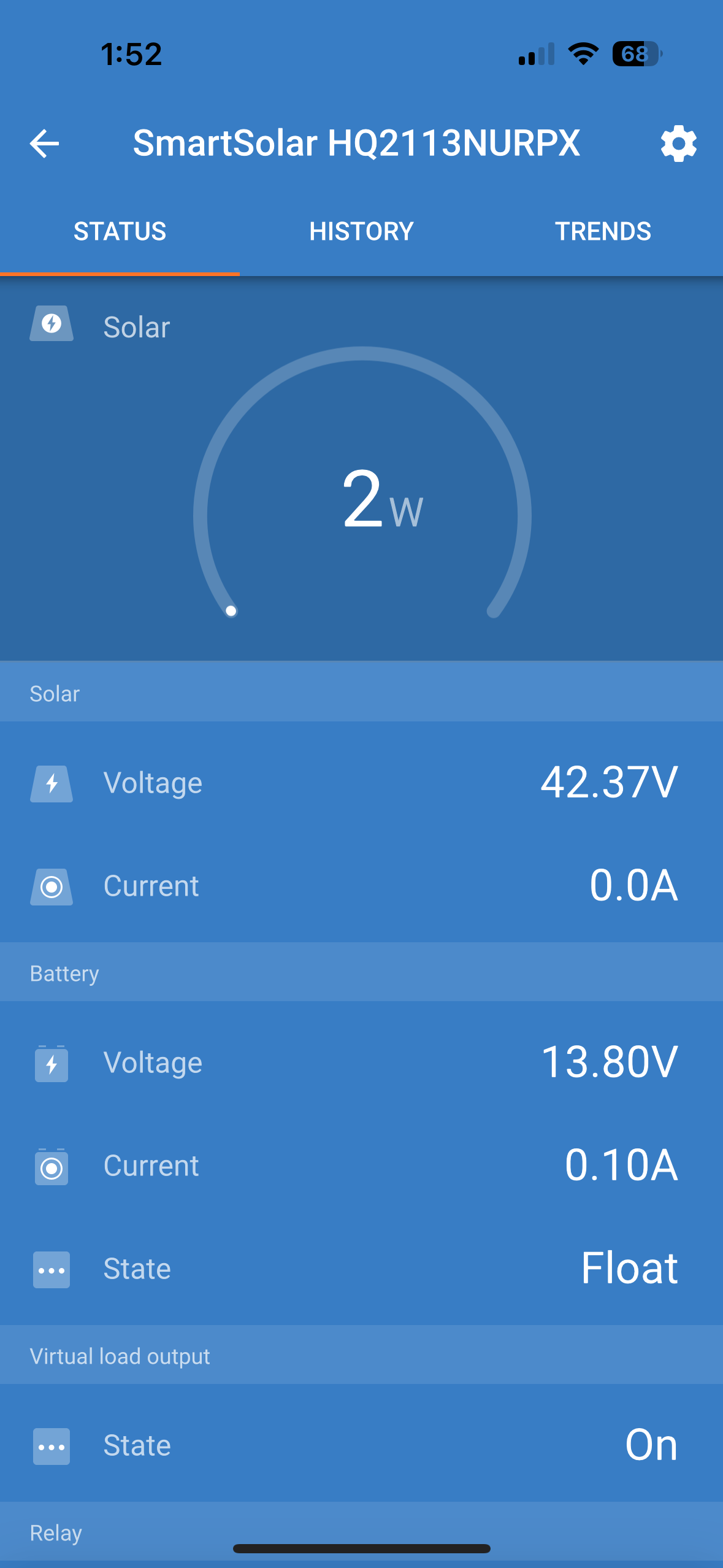
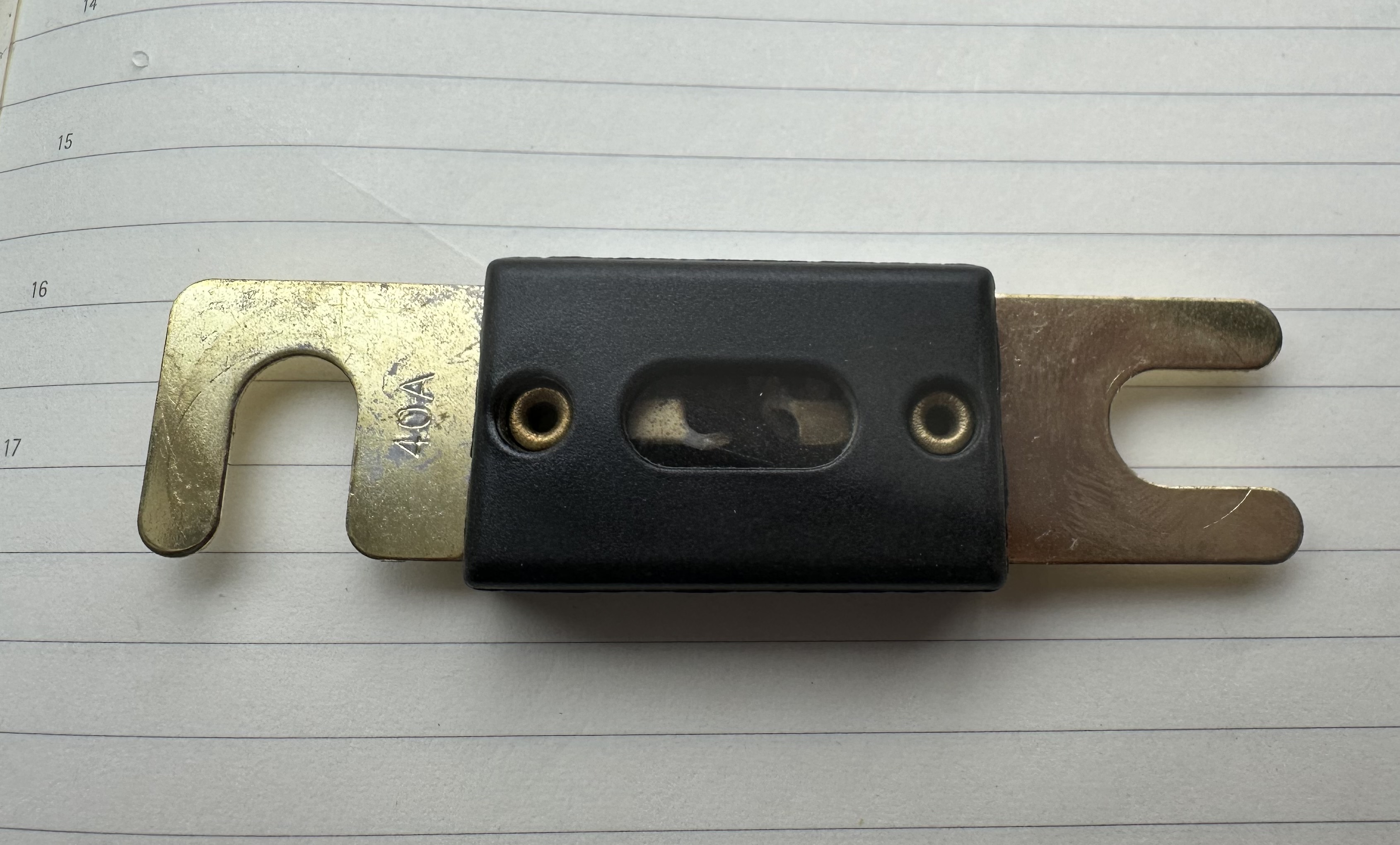
No problems until today. 1000W solar panels Vmp 38V Imp 25.6A with Victron SmartSolar 150/70. Today I see 43V in on VictronConnect and VRM but no amperage and no watts despite Phoenix sun. Measured voltage at PV terminals - get 52V and 24.2A. Also all solar fuses are not burned out.

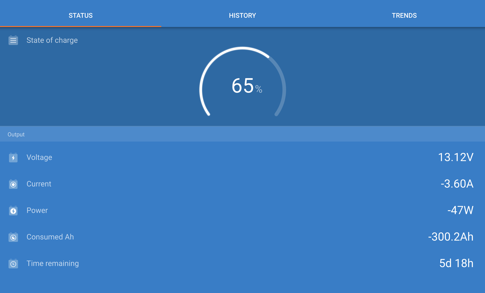
Checked the system on VRM:

1. no new notifications

2. No errors

3. No new firmware updates

i reset the Victron SmartSolar and watched it go from Bulk, then to Absorption in 2 minutes, then to Float and see no solar wattage or amps in.


Any ideas or suggestions?

img-5263.png


MPPT SmartSolar
img-5263.png (157.0 KiB)
2 |3000

Up to 8 attachments (including images) can be used with a maximum of 190.8 MiB each and 286.6 MiB total.

8 Answers
regman54 avatar image
regman54 answered ·

At 13.8v it would appear the battery is fully charged thus why the charge cycle quickly went through Bulk, Abs, then to Float mode. If so that's normal behavior.

2 |3000

Up to 8 attachments (including images) can be used with a maximum of 190.8 MiB each and 286.6 MiB total.

pwfarnell avatar image
pwfarnell answered ·

Either your batteries are full so they do not need anymore charging so no solar input required or you have a poor connection between your MPPT and your batteries. Use your digital multimeter to measure the voltage at the battery terminals and compare this to the MPPT output. If they are the same the battery is full, if the battery voltage is lower check all connections, isolators and fuses.

1 comment
2 |3000

Up to 8 attachments (including images) can be used with a maximum of 190.8 MiB each and 286.6 MiB total.

pwfarnell avatar image pwfarnell commented ·
You could also try drawing a load from your batteries, if you do the solar output should increase.
0 Likes 0 ·
robkhoo avatar image
robkhoo answered ·

Thank you…the MPPT does show 13.8V but my SmartShunt shows battery at 65% capacity and 13.12V - a clear dis-synchronyimg-0192.jpeg


img-0192.jpeg (296.9 KiB)
3 comments
2 |3000

Up to 8 attachments (including images) can be used with a maximum of 190.8 MiB each and 286.6 MiB total.

pwfarnell avatar image pwfarnell commented ·

As noted above you need your multimeter to find where the voltage drop is occurring and sort it out, we see this issue on the forum from time to time.

Do you have resettable breakers like the ones shown, these have a reputation for generating high voltage drop due to poor contacts.

61hc4vz2ewl-ac-uf8941000-ql80.jpg

1549019884-74727400.png

1 Like 1 ·
robkhoo avatar image robkhoo pwfarnell commented ·
Yes….the lower one. What do you recommend as a replacement?

How does a breaker cause dis-synchrony between the 13V I measure at my battery bank from what the MPPT sees?

0 Likes 0 ·
robkhoo avatar image robkhoo robkhoo commented ·
And this is the first time I have seen this lack of synchrony in the two years I’ve had this system
0 Likes 0 ·
robkhoo avatar image
robkhoo answered ·

I measured the voltage of my 12V battery bank - 13.0V

2 |3000

Up to 8 attachments (including images) can be used with a maximum of 190.8 MiB each and 286.6 MiB total.

kevgermany avatar image
kevgermany answered ·

Resistance in the breakers causes this. Using the breakers under load, even infrequently, causes arcing which burns the contacts and causes resistance or no contact.

Replace with a proper solar isolator switch. In general leave panels switched on unless there's a good reason to disconnect

2 |3000

Up to 8 attachments (including images) can be used with a maximum of 190.8 MiB each and 286.6 MiB total.

pwfarnell avatar image
pwfarnell answered ·

That type of breaker is a thermal breaker and works as it heats up with high current, but if it is in a hot location it can start to lose contact giving high resistance. As you battery system is 12V you could use a standard isolator and a fuse and the fuse should be 80 or 90A.

12voltplanet.co.uk/bep-701-contour-battery-masterisolator-switch-275a-

https://www.12voltplanet.co.uk/midi-strip-link-fuse-holder.html

2 |3000

Up to 8 attachments (including images) can be used with a maximum of 190.8 MiB each and 286.6 MiB total.

robkhoo avatar image
robkhoo answered ·

I may have been unclear…the circuit breaker with switch I use sits between the battery bank and the MPPT charge controller.

My solar panels have inline fuses and the incoming lines are on an isolator switch.

3 comments
2 |3000

Up to 8 attachments (including images) can be used with a maximum of 190.8 MiB each and 286.6 MiB total.

Alexandra avatar image Alexandra ♦ commented ·

@RobKhoo

Reverse polarity on the PV?

{Edited: Never mind. Its not a new install so wrong path.}

How did you get 24A on the pv when checking?

If it is reading the voltage incorrectly then it is time for a warranty check.

The pre RMA is here.

0 Likes 0 ·
robkhoo avatar image robkhoo Alexandra ♦ commented ·
My solar field has two parallel string with the Imp target of 25A.
0 Likes 0 ·
Alexandra avatar image Alexandra ♦ robkhoo commented ·
Ok, so not measured but theoretical?
0 Likes 0 ·
robkhoo avatar image
robkhoo answered ·

Thank you responders in the Victron Community for your quick timely responses.

I found the problem and fixed it. Always always when there is a problem, inspect the entire system and invariably the problem is something simple...not reseting the MPPT to default settings or replacing the solar charge controller or other expensive solutions. As usual, the problem was a fuse in the positive line from the battery bank to the MPPT battery terminal.

That 40A ANL fuse was burned out - no electrical continuity was found.

It is almost always a fuse problem.

I replaced the fuse, established continuity between the MPPT and the battery - now the battery bank is charging with the beautiful blue light on!

Thanks.img-5265.jpeg


img-5265.jpeg (1.2 MiB)
2 |3000

Up to 8 attachments (including images) can be used with a maximum of 190.8 MiB each and 286.6 MiB total.