 I
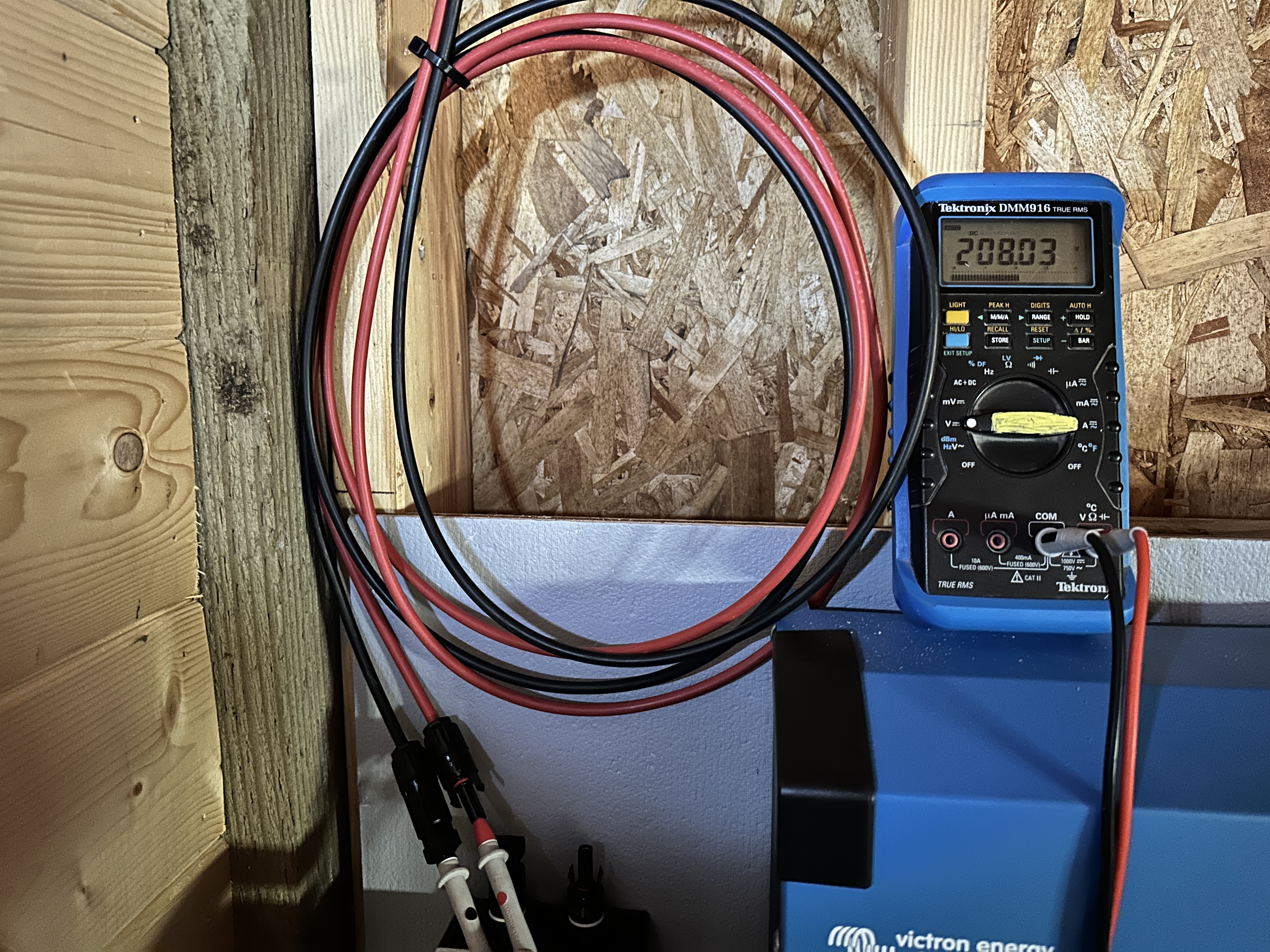
I  connected my pv string to the MPPT 250/100 48V system. The pv wire reported power 208V, I connected to the MPPT it showed no voltage, thus no charging to my battery. The negative port seems to be a problem. I could take the neg wire and test voltage showing at the wire tip and the MPPT pos port. Is there anything else I need to do to turn it ON?
 System
Thanks
asked
Smart Solar MPPT 250/100 cannot see PV power to charge
So my MPPT problem turned out to be a Victron defected MPPT. It is under 5 years warranty. I received the new MPPT, connected it in and it charged the battery bank. The service manager mentioned the symptom looked like an internal short in the MPPT.
So when in doubt, bring back the MPPT to the distributor.
I have been having exactly the same issue and have pretty much replaced everything from the PV panels to the MPPT. Just could not understand why the voltage "dissapeared" when connected to the MPPT. I also did not believe that the Victron was at fault as it would still connect via Victron Connect App etc. Only after i plugged the PV wires into my Fronius inverter as a second string did i realise that the problem is in the MPPT. I wish i had read this post sooner as it would have saved a lot of time and money on new cables.
Are the wires correctly connected at that PV disconnect switch?
You measured the PV wires as they entry into the disconnect switch and there the polarity is correct.
But maybe the outputs from the disconnect switch are reversed. Usually IN/OUT are in "X" pattern (top-left connects to bottom-right and top-right connects to bottom-left).
Or the proverbial clamped on insulation problem has occured?
Other funny one I have seen is the cable was inserted behind the rising clamp... So not clamped correctly.
I took out the negative lead at the MPPT neg port and measured from the lead to the breaker to the MPPT pos port and it read voltage - 205V, etc. Put the neg lead in the port and it reads no voltage. I check to make sure no insulation crimping in the neg port and even touching the port metal clamp, it read no voltage. The copper wire was pressed down flat so I know it made contact.
I made a new wire and it behaved the same. I am stumped. Does the MPPT need grounding?
I don't understand what you measured there.
Just remove the PV wires from the MPPT PV terminals (while removing the wires, disconnect the PV, because of dangerous voltage).
Then measure with the multimeter between the PV wires (after reconnecting the PV), at the wire ends which insert in the PV terminals of the MPPT (but without the PV wires inserted in the MPPT).
Especially check the polarity. Red positive/black negative.
Also not 100% clear if the MPPT itself is working. By this I mean when the MPPT is connected to the battery, can you access it with VictronConnect on a phone?
I checked the internal wires. They didn’t cross.
The voltage polarity confirmed they are not crossing.
@James Nguyen Have you checked your MC4 plugs? I had 1 crimp not lock in properly and give a high resistance connection.
Resistance of both Pos and Neg wire measurement are low ~0.18 to 0.22 ohms. No high resistance
I measured the voltage across the pos and neg leads to the MPPT, there was voltage from the PV as expected. Just connecting to the ports, no voltage reading.
Turn everything off (disconnect the PV then the battery) and measure the resistance from the top switch to the MPPT on both negative and positive wires and report back. You can then work backwards till you find the problem if that is where it is.
And/or...
Still with everything off measure the resistance from negative to positive first with the negative and positive connected to the MPPT then with both disconnected and report back all reading please.
Sometimes voltages can be misleading (you can have volts but only when put under load does a bad connection show) and faulty equipment can pull the volts down, measuring the resistance will lead to the fault/problem.
Hope this helps a bit.
I measured the resistance of neg and pos path from the cut off switch to the lead feeding into the MPPT. Neg path reported 0.18 ohms and Pos path reported 0.22 ohms.
One test I measured the voltage from the MPPT Pos port with the Neg wire lead, it reported 205V which is exactly the same from the PV. I reversed the test with the Neg lead connecting to the MPPT Neg port and Pos wire - No voltage.
From this test, I think the MPPT Neg port is the main problem
Is the MPPT on (connected to the battery and battery switched on)?
Use VictronConnect to connect to the MPPT and check there for error and the correct settings.
Also check this:
Also not 100% clear if the MPPT itself is working. By this I mean when the MPPT is connected to the battery, can you access it with VictronConnect on a phone?
No answer on this question.
If you can connect with a phone, does it show any errors?
VictronConnect worked. It updated FW twice. I was able to change the battery type and BT pin, etc. It also recognized the battery power correct as the BVM 712 reported.
I reset the MPPT to factory default twice, same problem occurred after resets.
Remove everything from smartsolar and with a multimeter on diode mode measure pv in and battery in both sides. Maybe it’s internal fuse on pv in.
I have same 100-250 i have simiral problem was in MC4 plugs, i change it and worked!!
Try inserting your meter leads into the PV terminals, from the bottom. The same place your PV (+) and PV (-) wires are inserted. Do you see 200 volts DC there? Get an "inspection" mirror and a bright light so you can see and know for a fact that your PV wires are inserted and clamped properly.
I did measure from the bottom and the voltage reported the same as the front ports - & +
I did turn the MPPT sideway to probe the PV ports. I could see the metal to probe. Touching the metal or the lead didn’t change the voltage to above 0.
I would think touching the wire lead inside the port should read voltage as it was not connected but still no voltage whatsoever. Take the negative wire out, probing the positive port and the negative wire, then there is 200V.