Hello - I am struggling to find someone who will fit a Victron ESS (Quattro 8 KVA 48V) with 16kWh of BYD batteries. Plenty of PV suppliers willing to charge me £5K plus for the installation (plus another 12k for the kit itself). Anyone know an installer/electrician who can do this in Surrey for a reasonable fee? I am inclined to split the supply of the inverter/charger from the PV as it feels like I am being quoted a fat margin on top of subcontractor fee
asked
UK ESS Installer in Surrey/Home Counties
Just ruff clac your looking at 9plus for the big bits of kit, it’s really not cheap plus all the other little things that add up, as I’ve been doing mine myself I know the cost mounts up really fast. Sorry can’t help with the installer. but maybe buy the bits then get an installer that’s charging you 5K to install?
Glad to know I am not the only one with this headache. Thank you
@Nick Neil-Boss I'm on a the same boat. I've found an installer that looks pretty promising. Will let you know how the install goes (when they get back to me).
If you don't require MCS certification, then you have more options. As i've found several electricians (qualified & competent) to install the victron system.
That would be very helpful . Many thanks. I am not too bothered about MCS as it does not appear to be mandatory. More keen not to have someone unqualified make mods to my supply. Will DM you later (presume that is possible on this formum)
No DMM facility here. But if you use
@Nick Neil-Boss as before he will get an email notification.
I did the setup myself after facing the same issue (ESS with no feed in enabled + PV) - installers only want to fit kit that they supply.
If you are happy to go the zero export route then the victron kit is really easy to install especially if you're open to have someone explain/walk you through the basics of how it all works.
That's what I did - then got an electrician to install the ET112 meter and wire the inverter into the mains (Multiplus II).
Happy to share my direct experience if its of use?!
I am doing this with the object of 100% self use of any generated PV energy, so zero export is probably OK. Unless I cut the install cost, the economics looking really shaky. Would appreciate your experience. I am an electrical engineer by original training, so none of this is rocket science to me, but not an electrician to keen not breach any regulations . I will DM you later if that's OK
Hi @Nick Neil-Boss I don't think you can DM on here but feel free to email me;
tobias.j.franklin@gmail.com
also here's my schematic that details the install https://drive.google.com/file/d/1zi8Bp_9hH0nR8bJunU8fBMhhI_5dYI_e/view?usp=share_link
As I understand it zero export via either being off grid or via zero feed-in with anti-islanding (which the multiplus does natively) then you are within the rules of non MCS sign off. If you are connected to the grid still like I am then I believe there is still a limit on the inverter capacity to 3.5kva which your Quattro exceeds.
So you would HAVE to go the off-grid route (as I understand it).
This video is also really useful https://www.youtube.com/watch?v=CgDcvJsrQHw
Hey
@Tobias Franklin this is super useful! Out of interest, which tool did you use to create the schematic?
Online tool called lucidchart (I have a paid account so not sure the free version would let you use this many assets) - then I just google searched for the images and screen shot/cropped then paste them in, (a lot of the time there's a nice vector image in the victron manuals).
You can also download draw.io which is the same as lucid chart but free and will get you exactly the same results.
As @dmsims has said there is no limit, just the way it’s applied for G98 can be installed and just tell the DNO after G99 for anything over 3.68 needs to get permission before connecting to the DNO network. you will need to do a single line diagram of your network I have one floating about the forum have a look and see what they DNO need with this diagram
@Nick Neil-Boss @Shiv how have you guys go on so far?
Hey
@Tobias Franklin I'm still undecided. The installer that was familiar with the Victron system quoted £9k to install (with me supplying all the kit. So, 4kwp panels, 5kw multiplus II gx and pylontech 3x 5kwh). So this plan has gone down the drain.
I'm reconsidering the PVs and leaning towards a battery only system for now. I'm on Octopus intelligent (so 7.5p for 6 hours at night).
I'm reconsidering the PVs and leaning towards a battery only system for now. I'm on Octopus intelligent (so 7.5p for 6 hours at night).
As much as I want the Victron system, I'm struggling to make the numbers work out.
That’s shocking! They are just trying to rip you off or giving you a silly quote because they don’t really want to do it.
If your panels are on a garage roof for example I promise they are not too hard to DIY
If on the house yes of course you need them professionally installed!
If you would like a hand with the equipment setup just let me know. To add the panels later will be very easy and at least you will be saving immediately on your bills!
15kwh will get you through a day/night cycle no problem! And like you said it may be the best economic route to take anyway given you already have super cheap night tariff energy!
Yeah I had a feeling they weren't too keen.
I had a look at your diagram and it gives me quite a bit of confidence. I'd love to pick your brain on the equipment setup!
If I'm going Battery only (and say I start with a single US5000). I'll just need the MultiPlus-II 5kW GX, ET112 and US5000, with a DC isolator and an AC Isolator?
I'm presuming I don't need the Lynx Distributor?
I'm reasonably familiar with the DC setup. It's the AC side of things, that I don't quite understand yet. I do plan to get a qualified electrician to connect the setup to the grid, but I'd like to understand how it all works, so I can explain to the electricians.
After the ET112 and the RCBO? do you just connect it to a spare connection in your consumer unit?
Or do you split the incoming AC after the supplier meter with a henley block?
Yeh pretty much - I would set things up with a bus bar though because its where your fuses go and it will make things easier for later.
You don't have to use the Lynx, you can get any suitable busbar for 1/4 the price from https://climbingvan.co.uk/product-category/electrical-system/accessories/bus-bars-fuses/?filter_product-type=bus-bars.
I have mine on the circuit that goes out to the garage. So its downstream from the consumer box which means no risk of overloading. So that circuit is on its own RCBO already so no need to add anything else.
On the AC side if you're downstream of the consumer box the AC-IN is actually an input AND an output. Power can flow in both directions at the same time and that's why you have the ET112 meter so that the inverter can ramp up/down to meet the pressure so that you maintain a small draw from the grid up to the max capacity of the inverter.
Its literally a single branch off of the garage mains supply running into the AC-IN via an AC isolator and you're off.
//
If you're installing inside the consumer unit location then you can also run the initial mains into the AC-IN and then out of AC-OUT-1 - this way the inverter can perfectly balance itself.
Then you don't need the ET112 but you have to be very careful not to exceed the output of the inverter because that would cause it to break/shutdown.
--
This video perfectly describes your options https://www.youtube.com/watch?v=CgDcvJsrQHw&t=2s
That is totally shocking for the install cost!
Battery only can work by the way. I have a Multiplus II 3000W in my campervan. There's a wireless Zigbee/RS485 link between the ET112 meter next to my consumer unit and the Cerbo in the van. It charges at night on the 7.5p rate and powers the house most of the day. The van is literally just plugged into regular plug socket via an Electric Hook-up cable (that you'd use at a campsite).
I'm not sure I understand... Do you mean it's a V2L setup? I'd be super interested to know more!
Sounds like he has a 'mobile setup' so it runs off grid when he's on the road and then wires up to the house with a 32 amp plug and sets the Victron ESS assistant on.
Which is then talking to his house via the ET112
@pau1phi11ips gotta say that is absolute genius! I guess you have a couple of panels on the van that contribute a little bit?
@Tobias Franklin Yeah, 600W solar on the van. I get 3.5kWh from those on a good day.
Van is on a 16A connection. The Multiplus is set to 2500W max feeding back into the house so it doesn't stress it.
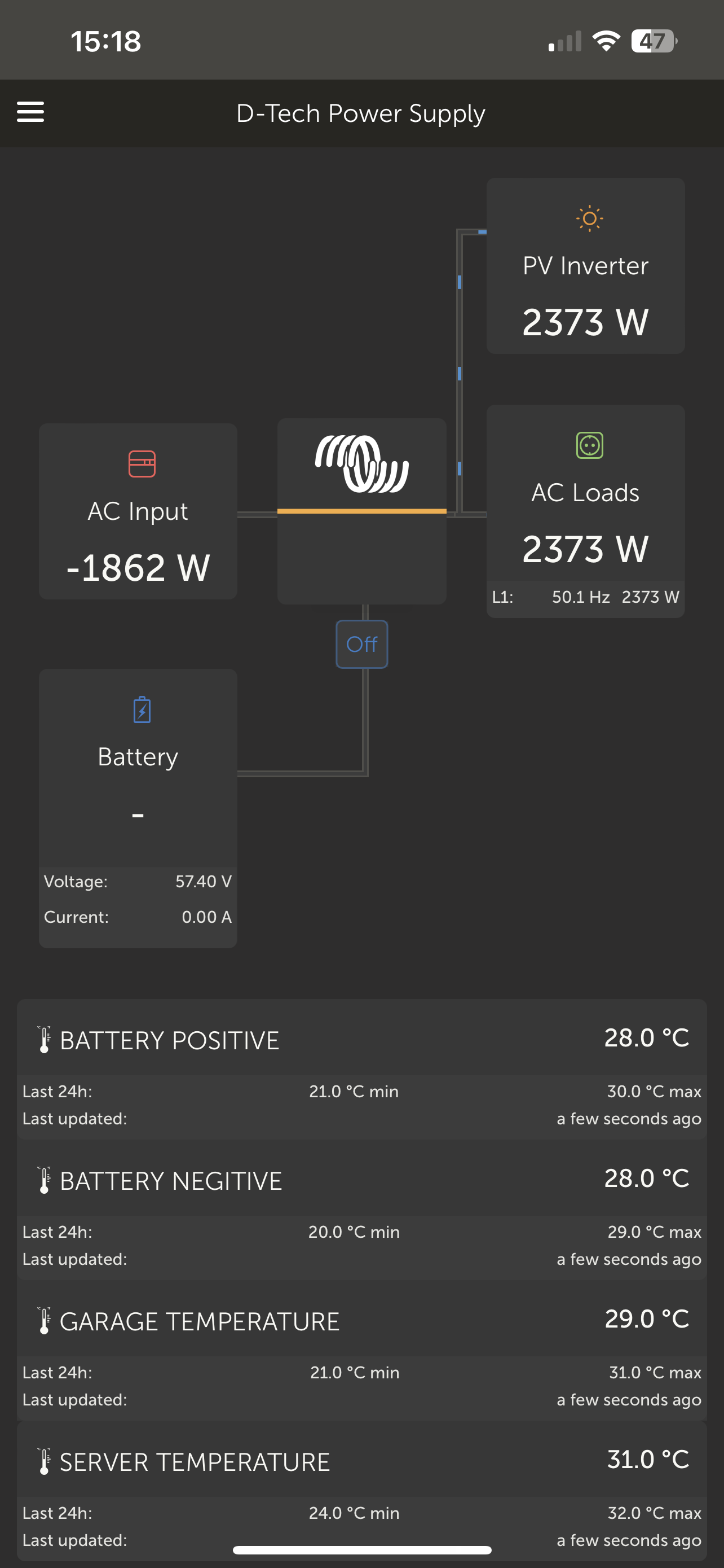
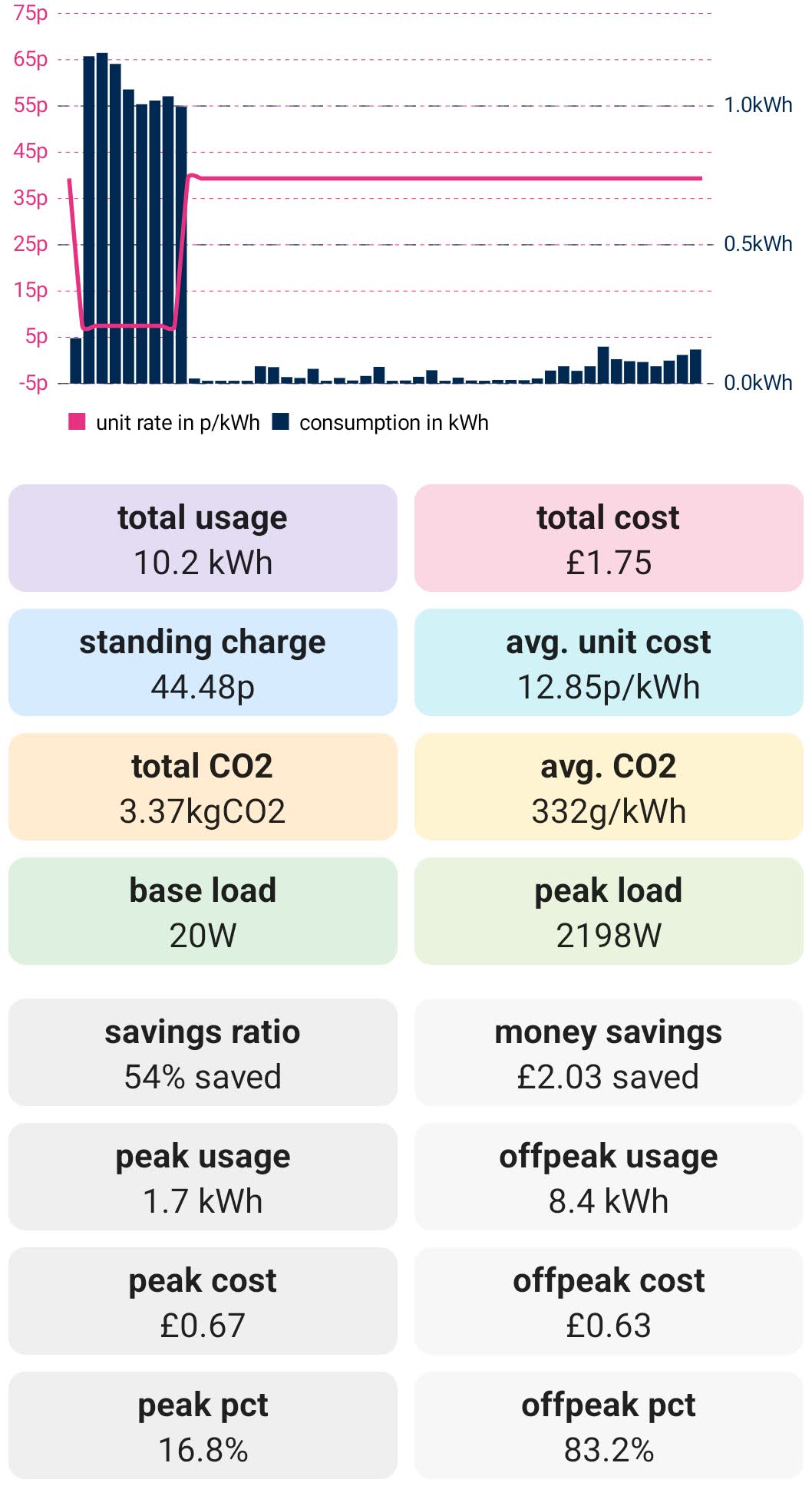 Yeah, V2L. I've got 7kWh of LiFePO4 in the van. My house uses ~10kWh/day . On a sunny day the 600W of solar on the van and 600W in my back garden on a small Grid-tie Inverter make up the difference so pretty much all my grid usage is during the 00:30 - 04:30 cheap rate from Octopus. The attached image is my grid usage yesterday. You can see the van battery ran out about 8pm.
Honestly, this is super impressive! well done. Do you have any pictures of the van? I'd love to see the PV's and the battery!
Some photos from when I was building:
https://photos.app.goo.gl/j5zpxefKxFXzK9X2A
I haven't got any recent ones now it's neatened up a bit more.
I left room for a second Orion charger but after installing the 600W of solar, I don't need it. I usually leave the Orion turned off.
The battery is built using 8x 280Ah cells from China. I tested them before it was built and got over 270Ah each so happy with that. Cost £800 inc delivery in 2021.
Going nowhere fast! Back and forth between using an installer vs doing it myself. PV and offgrid installers obviously too busy to respond in a timely way or with sensible labour costs. Supply and demand at work. What I might do is follow your suggestion and just do the Quattro and battery for now, get the Octopus night tariff and bide my time on the PV - considered doing panels myself but lack the equipment and experience to work at height. Would appreciate a discussion offline with you Tobias sometime.
@Nick Neil-Boss yeh sounds like a good idea - the panels are easy enough to fit if getting up on the roof space isn't really difficult. I put mine on the garage and just added some more recently to a small lounge extension. Both are are easy to get up onto with a ladder. Absolutely a 2 man job though!
But an actual roof you absolutely want a professional doing that. You might get a reasonable quote from a roofer?
(tools wise you only need a decent ladder, slate ripper, impact driver to get the racking up and the panels locked down).
//
I think your experience is universal across the country at the moment. Companies only want to install the kit they are used to supporting and not stuff people have acquired. I had a brief panic that I wouldn't get mine done. It was only with the help of a good friend that meant the panels went up (the hardest bit really as everything else you can 'follow the instructions on').
And sure tobias.j.franklin@gmail.com anytime
Just to note that if it is installed with panels I dont think you pay VAT on the whole system. So could save you 20%
To the foregoing I would add that since "I am an electrical engineer by original training, so none of this is rocket science to me, but not an electrician to keen not breach any regulations" you can regularise the position by doing your own install under a Building Notice and then getting it inspected by the LA, they are usually quite helpful.
DNO won't care if it is MCS, and are relaxed about self-install IME. Plenty of help on here about completing their paperwork.
IET Code of Practice tells you much of what you need to know and you can borrow it from their library if you are a member (but doesn't exactly cover typical Victron install scenario).
In any event familiarise yourself with their earthing requirements which are quite complicated but free to download.
Word of warning though, I spent much of last year finding someone who would install additional PV on an existing Victron setup, either they were not willing to forego the profit or they cited complications about warranty if the kit was not all supplied by them.
So if you can afford the time I would suggest you get the PV installed first as a basic 3.68 kW grid-tied system. If you want more than that then maybe get them to put up and test the panels and leave them terminated at a DC isolator till you have the Victron kit.
I've had a couple of people on various forums suggest going directly through local building notice. I'll need to check how much more work it will take on my side. I suspect it will certainly be more cost effective.
On the PV side of things, I haven't found an installer that are willing to install the PV on it's own with victron either. The cheapest I've found for any PV is around £10,000 for a 4kwp ("tier 1 all black"), 3.68 givenergy, 5kwh givenergy.
Or £7000 without the battery.
It's an awful lot of money :(
I honestly don't care about the MCS certificate as I expect to be a net importer of energy with two EVs at home.
In the future, I expect I might have to "DIY" the PV installation, assuming I can sort out the access for a 3 storey roof.
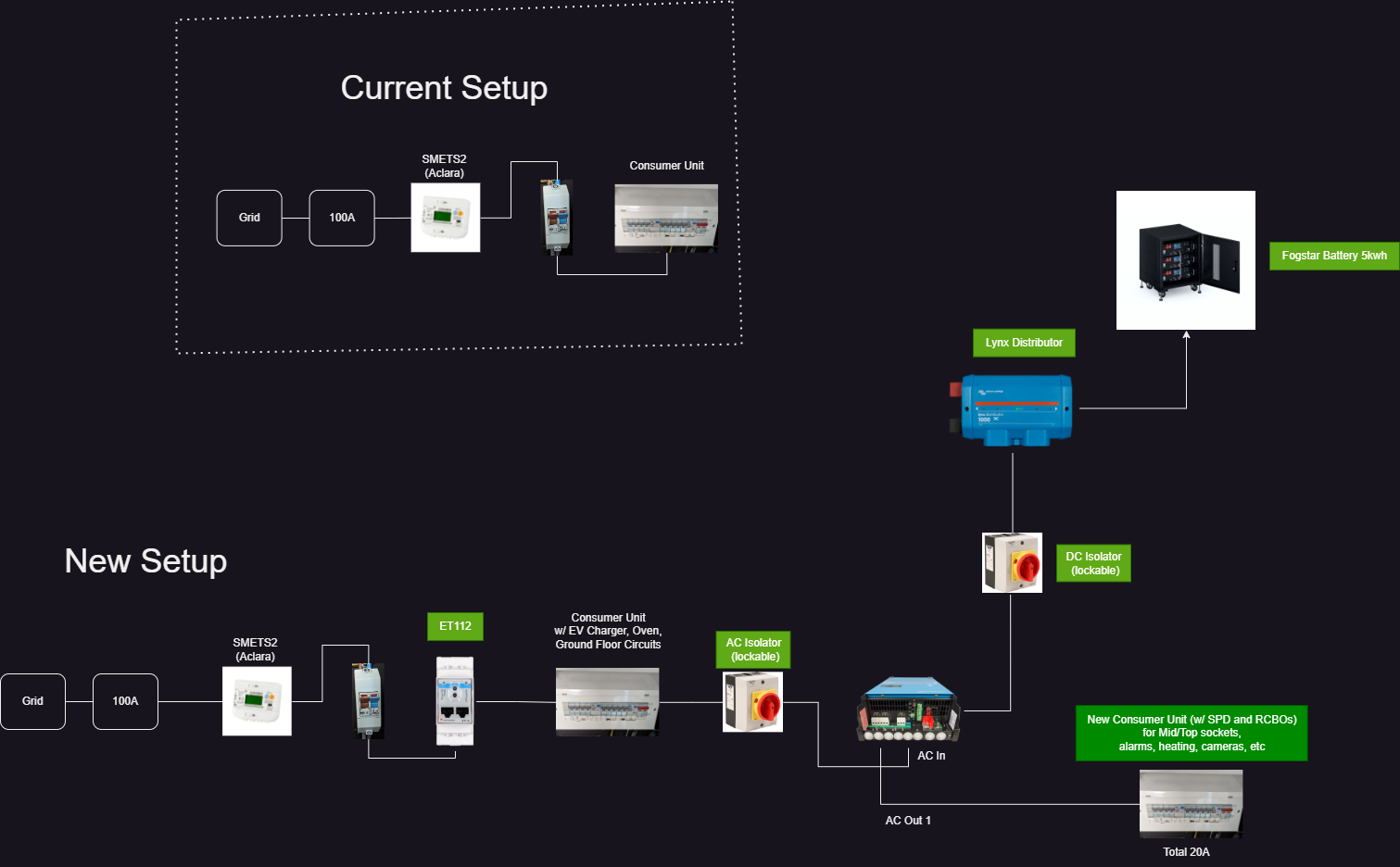
@Tobias Franklin Here's my diagram. Thank you for sharing that youtube video, it was super useful. I think I still need to understand the circuit protections and the grounding as per @sharpener post above. But does my block diagram look okay?
I could do the whole "single legged" approach, without the secondary consumer unit. Probably a lot easier to get started. But I'm not sure how much work it would be to later add the second consumer unit.
Also I have a suspicion that my current customer unit (which only has one spare slot), is probably not sufficient even in the "single legged" mode?
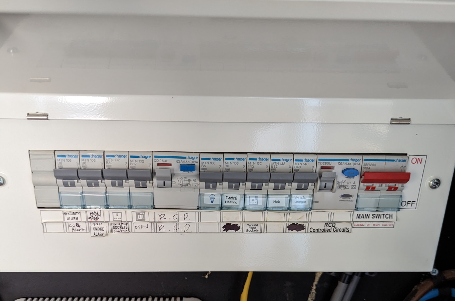
I would change the MCB’s for RCBO’s and then throwaway the middle RCD as it’s an AC type not good when DC current is going through from others devices type A minimum now if you can stretch to two CU’s and replace that for a bigger Hager unit with and SPD then I would are you starting to see where this money is starting to go? Things that you haven’t accounted for start adding up. I don’t really want to do a total for mine until i get batteries as I may pop a vessel.
Hi @Shiv yes that diagram works fine. AC-IN will be your bi-directional and AC-OUT-1 will be your protected loads up to 20amps.
My unit setup is exactly the same as yours - my equipment sits in the garage which is on the consumer unit protected by a Hager MTN 116 B16 RCBO - the inverter output is within this as I have the 3000/48 model (3680w). If your inverter is bigger you may want to fit a different RCBO onto that circuit.
I used to have mine essentially set up in a similar way except I just connected the AC-OUT-1 to a double 3 pin outlet that I could plug things into in the event of a power cut (never really experience them around my way so didn't bother going as far as adding a new consumer unit like you plan to).
I since relocated that outlet to AC-OUT-2 which is programmable and have a 3 pin EV charger linked up so I can take advantage of SOC information for turning the charger on/off. And thus charging the car off of solar at the rate that my panels produce it/inverter can invert.
I wouldn't worry about the second consumer unit for now - you can always do that later, and better to get up and running with a phase 1 and then upgrade to phase 2 after I recon.
But yep you're all good!
(your ET112 meter might not fit in the box, in which case it can just go in its own box like this - then make a cable (I literally just used any regular 3 core for this) and wire it into your zigbee if you're using one or if your inverter is close by use the victron cable they make for this purpose and then the other end goes straight into the Cerbo GX).
@Shiv for all that is good in the world please dont attempt if you’ve never done AC electrical work, as @sharpener said earthing is a bit tricky given the kit that is needed to do the reading and make sure the TT system functions with in the spec to cause RCBO’s/RCD’s to trip.
i have been in the same boat as you guys and just got fixated and read and planned out the install thinking of things that I would need what I could get away without doing mmmmmm! Ended up adding lots of other stuff and then having to go over stuff when I thought I could do without the ET112 on the solar good job I’m not paying anyone.
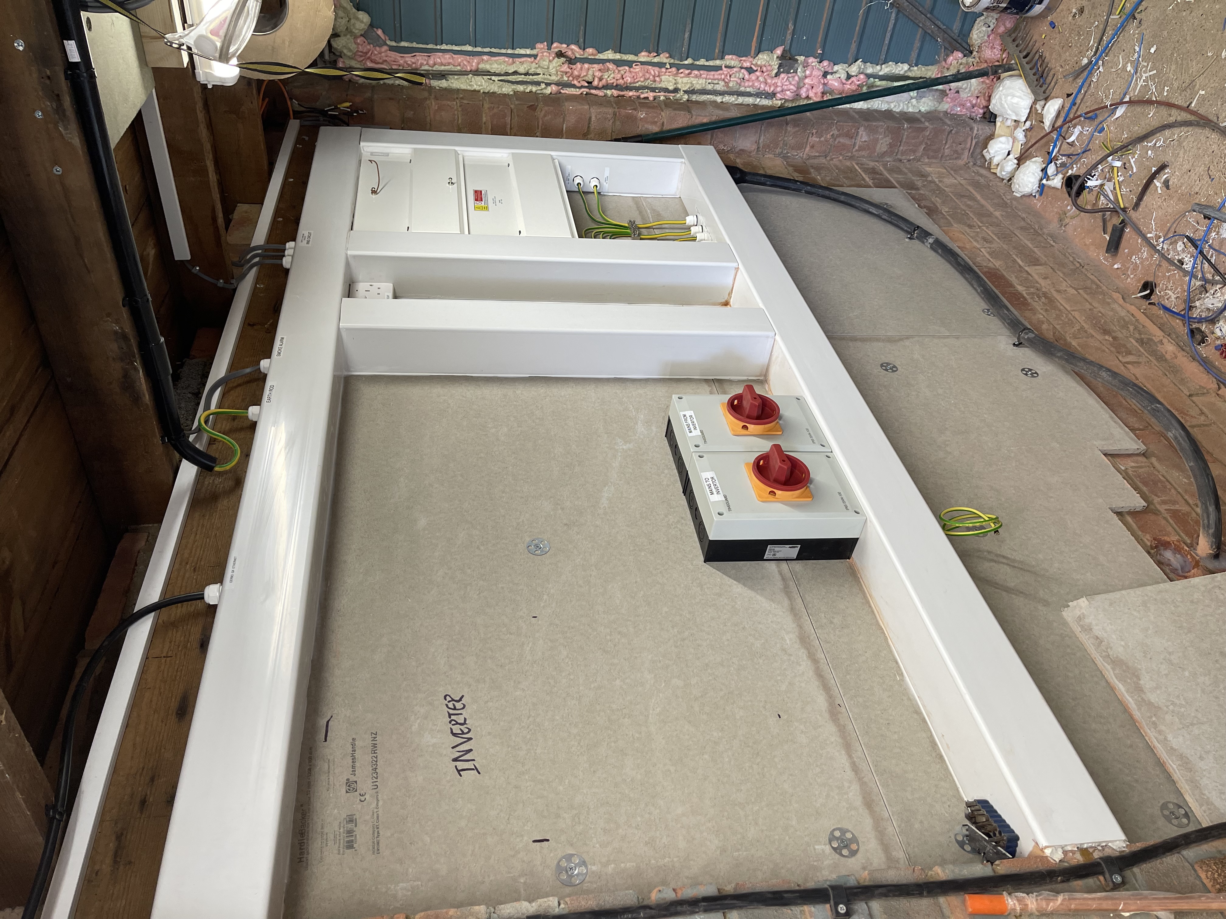
I would say look at the space you want to install it. look at all the system designs on this forum think about your CU layout how is the output power being used where is that going to terminate? Build a precharge circuit into the system, think about temp sensors what kit you need what it does and then you’re on your way to doing your system. I thought I could just give the system a small space but glad I expanded it as I added more stuff than I actually designed it to have. The beauty about doing the system yourself you can work on it as much as you want without trying to rush a finish. I think I’m more or less done with my build just batteries needed now. Take a look at what I’ve done it would give you a better picture. Ignore the red black wires at the cerbo I was waiting for additional temperature sensors and the cable going to the Lynx distribution is just so I can power up the Cerbo until I get batteries.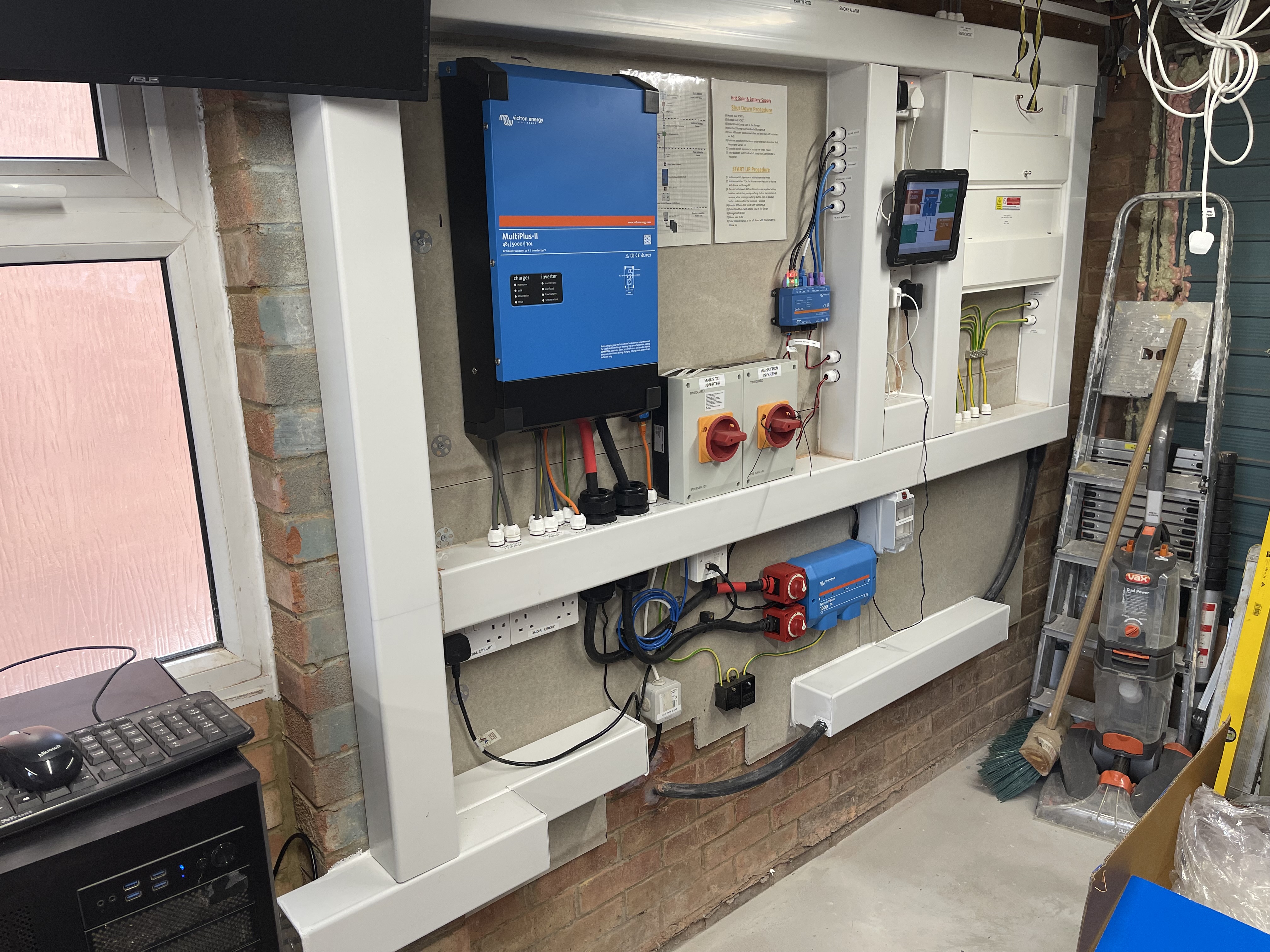
I hear you @Daza. As of now, all I've done is draw a few boxes and lines on a paper. I don't intend to carry out the AC work by myself if I can avoid it. I have found a few local sparky's who are members of the competent scheme and can certify and generate part p (eic), who are willing to do the work.
So in all likelyhood, I will just employ one of them. However, I'm just trying to learn and understand the AC side of things, to make sure I can communicate my requirements effectively.
Your setup is mighty impressive. I'm working on a space that quite a bit smaller than yours. The MPII will be going under the stairs along with a battery rack.
The existing consumer unit is around 2-3m away along the wall. Probably will need to run the cable along the outside wall...
Do you mind showing me a picture of your consumer unit(s)?
Thanks, I would say get it all done in one ie second CU and doing it later is going to cost you twice! If you haven’t got much space you need to plan out all the kit to the mm.
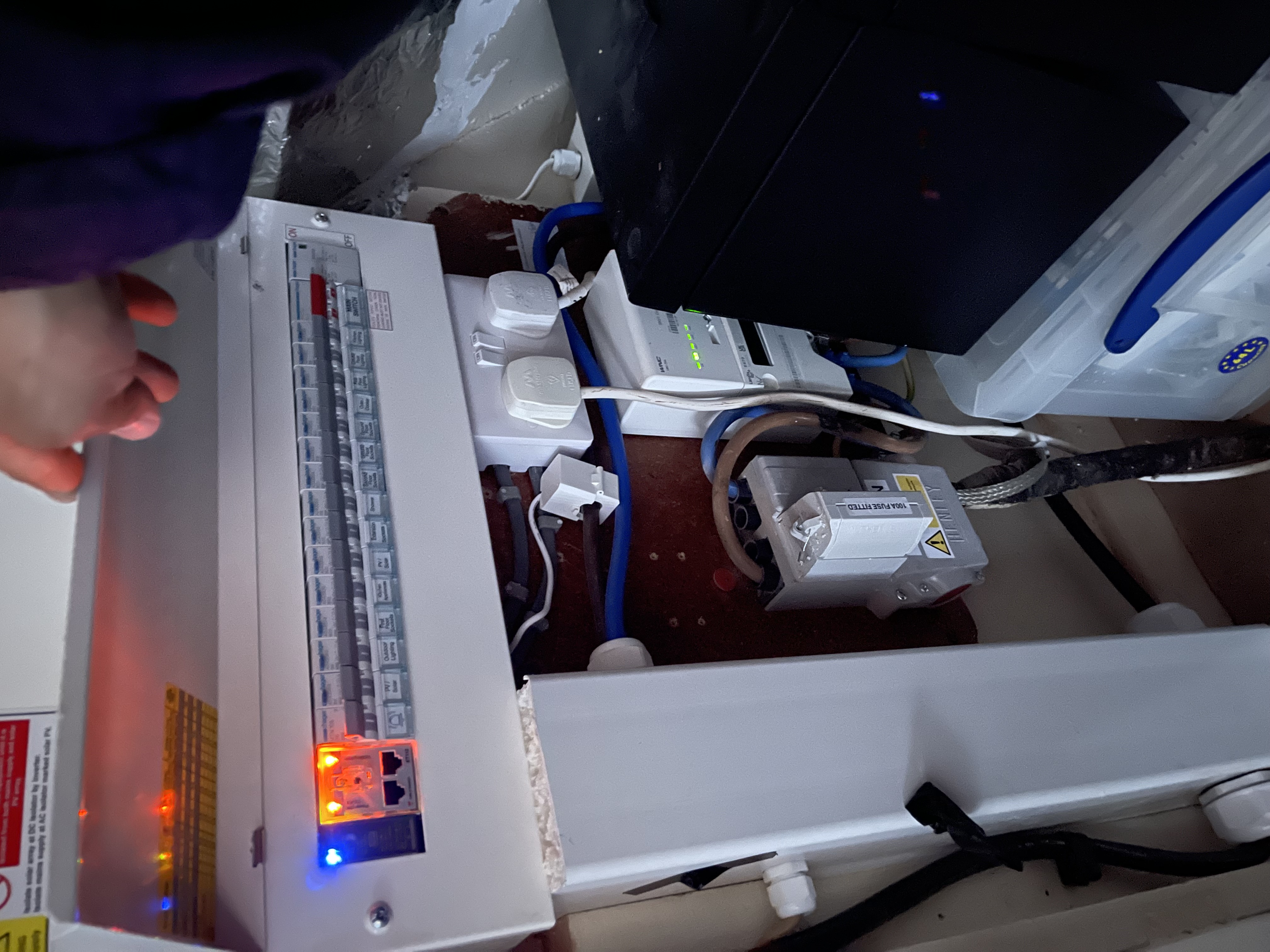
My CU’s not got an open one on the garage CU though I take it that’s the one you wanted to see as it has the change over switch
This looks great. I don't think I've seen someone add a switches on both battery connections. What was the reasoning for this?
Thanks just for contro to isolate every point of the inverter from all power sources completely without losing the Cerbo GX ie if I had to do something with the inverter ie replace I’d rather have no voltage anywhere there, as a bonus gives me another point to monitor cable temp to compare them.
Some thoughts on the video and yr proposed installation:
For best protection the SPD ought to be at the incoming grid connection. The max recommended lead length is IIRC only 0.5m.
The Victron external CT responds more quickly than the ET112 so will give a better grid balance and is cheaper.
The input to the Multi needs to have its own 50A RCD (or DP RCBO) which is not shared with any of the loads. So for the single leg implementation you cannot just put it on an ordinary circuit off the main CU, which is what the video appears to say.
@shiv in addition to @sharpener I would not run the neutral through the ET112 it does not need it, it only needs to see a reference neutral and fused via a
100mA quick blow fuse @ejrossouw is correct it should be 315mA quick blow thanks. This only turns of the ET112 and does not stop the flow of voltage or current.
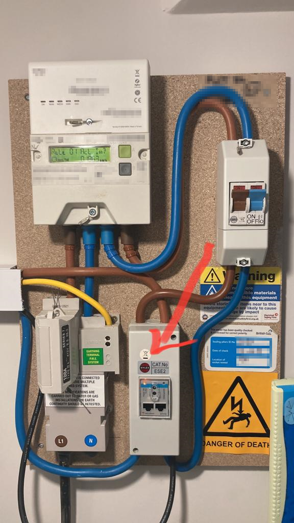
what you couldn’t see from the picture of my house CU is the ET112 fuse holder picture provided. Please do your research and due-diligence I’ve lost how many hours/days I went through the internet in order to plan the layout of cables and devices. Corrie the spark on YouTube done an install of an ET112 take a look. @sharpener does the current monitor not need to be wired now though for the DNO application? I got a lot of conflicting information regarding this in the end just went for the ET112
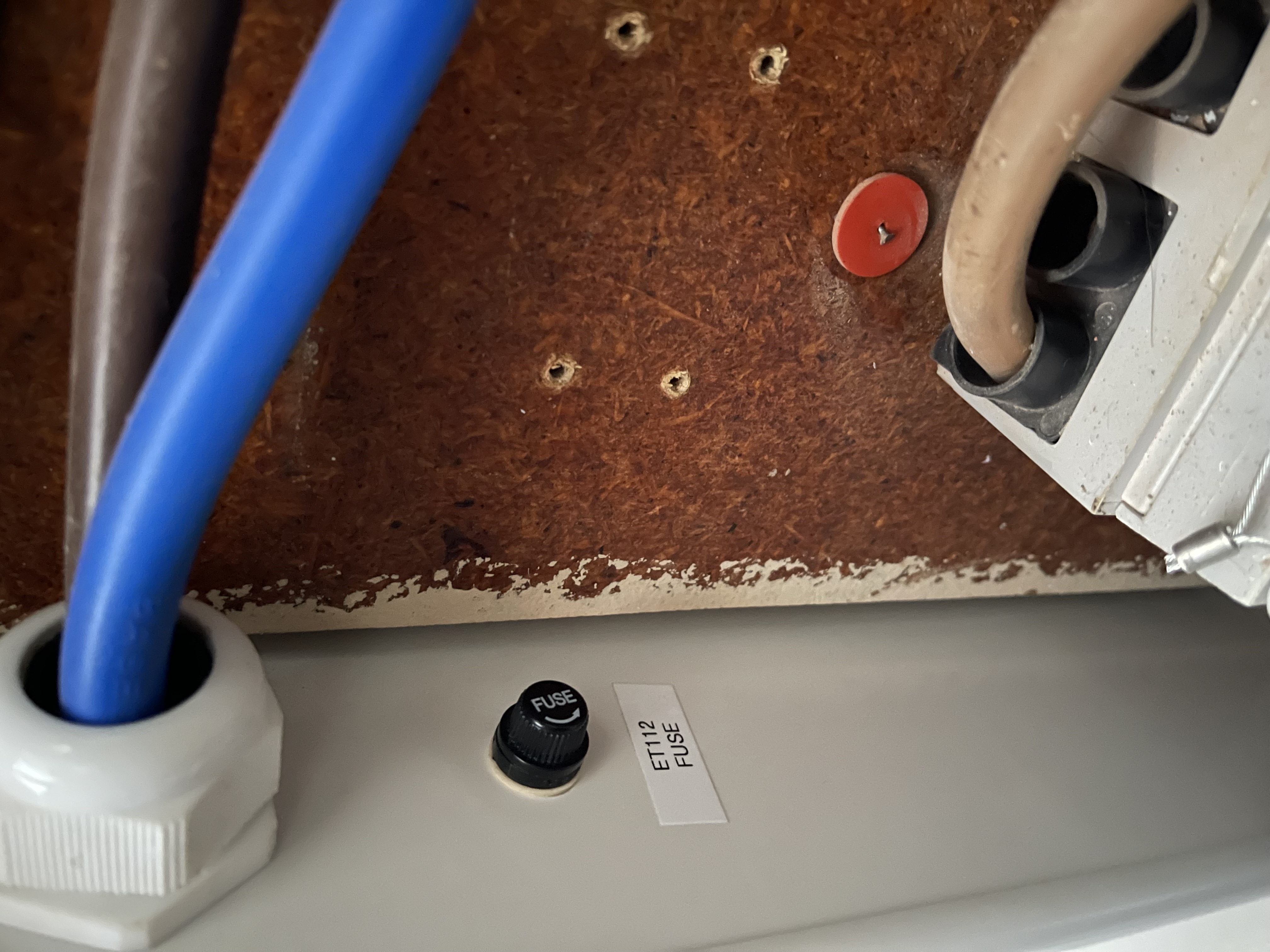
Victron‘s guidance on wiring and ET112
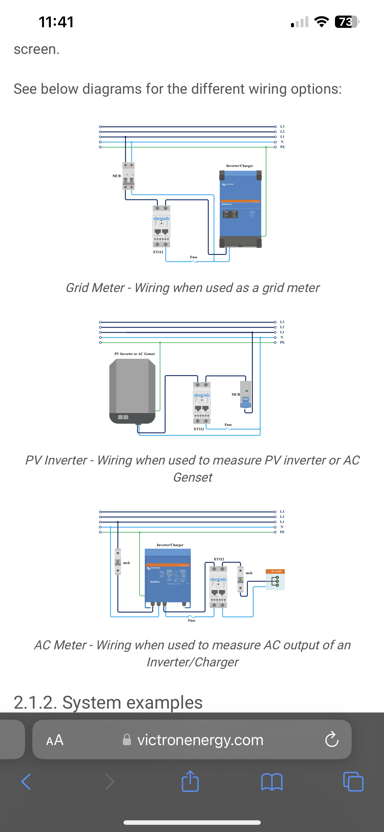
AC meter is inverter charge monitoring I wouldn’t leave it to the DNO’s 100amp, yes the ET112 can be in a separate enclosure but needs to be wired as they document and a suitable MCB used when going after the inverter or on the solar only exeption is grid monitor reference neutral only hence double pole isolation switch needed only hope this makes sense.
In answer to yr question @Daza I have the whole house after my multi, so the internal CT is sufficient and the DNO was happy with the description of that in the G100 section of the form. Don't see why the DNO would prefer an ET112.
Will have to change to an external CT when I fit a heat pump as this will be teed off before the multi, they are available much cheaper on Amazon.
I do have an ET112 but only for measuring the PV connected to AC-Out 1. In fact I have wired the neutrals through it because it is a convenient way of joining two separate lengths of cable, it is protected by a 20A breaker anyway. I did discovered if I wired in the termination resistor on the digital output as per its instructions it did not work but is OK without it(!).
@sharpener im sure I’ve seen/heard that new requirements is for wired monitoring, it may be convenient and you have it suitably protected with an MCB/RCBO no doubt, but I wouldn’t want the live and neutral running the whole house going through the ET112 even though it’s rated 100amp as the DNO fuse that @Tobias Franklin is likely break after that.
Why is it any dfffrent to the Meter on your house, that is not fused and has 100 Amp connected to it. Carlo Gavazzi is a very good brand and probably a better quality then you main meter.
@bm97ppc I hear what you are saying but (1) They don’t state that as a viable wiring option. May well be better quality than a standard meter but (2) The design of a standard meter its designed to link over live and neutral to the load and more substantial size connection blocks to enable high current over a prolonged time similar to a 100amp Henley block in make up and design of those terminals.
@Daza Victron might not show it as a wiring option but Carlo Gavazzi show it in there documentation (diagram 2a). This is an industrial device and would be rated above a consumer device for continuous load. A house is rarely above 40A for any length of time . This device is commonly used to monitor machinery and other applications running much higher loads 24/7.
That might well be in there diagram but for the application combination of devices it’s not documented, I wouldn’t say it’s industrial as industries meaning plant equipment which is not uncommon to use lot more amps than a 100amp rated device to run an industrial plant means this is not industrial use device domestic/light commercial sure, The company sure does make devices for industrial use but this device is not one of those. A house rearley goes above 40amps for prolonged times, this is not the case anymore and I think when designing an electrical system an EV charger should be factored in as a possibility/eventual add on of which the load is continuously there and in addition to normal house loads like the oven microwave airfryer all depends what you are doing ie what your cooking to how long it’s on coupled with the EV then it’s a sustained load over a long period.
Are you thinking of the requirement to have a wired i.e. not wireless connection to satisfy the G100 requirements for power limiting? Myenergi say you can't use a wireless harvi to monitor grid current for that very reason.
As the ET112 and the external CT are both "wired" for this purpose I can't see the DNO raising any objection.
Personally I would not be too concerned about putting 100A through an ET112, the connections are quite substantial. But I would rather use an external CT, as it is non-invasive, quicker to respond and cheaper. And does not take up as much space or need a separate enclosure. And the data connections on the ET112 are very fiddly, with the insulating spacer piece to cover the terminals and what not.
Downside to the CT is that the 3.5mm jack plug is not very reliable but they have now changed that.
Yes so I did get the wrong end of the stick with that. So I took it as because it was just an inductive coil and wired meaning the live has to go through the meter.
lol yes the Ethernet cable is fiddly to terminate in the ET112.
Mmmmmm when I look as a Henley and then look at the ET112 it puts me off especially when they don’t give it as i wiring option.