question

elel avatar image
elel asked

Discrepancy between Grid Setpoint shown in VenusOS and the actual power drawn from the grid (and some other problems in using ESS)

I am new to Victron products and have started setting up a 48V LiFeP04 battery system with a MultiPlus II 48/5000/70-50. In phase 1, my target now is to store electricity from the grid to the battery pack during low rate period at night and then use the stored electricity during day time. I am planning to add a PV system in phase 2 after I have got familiar with the Victron products.

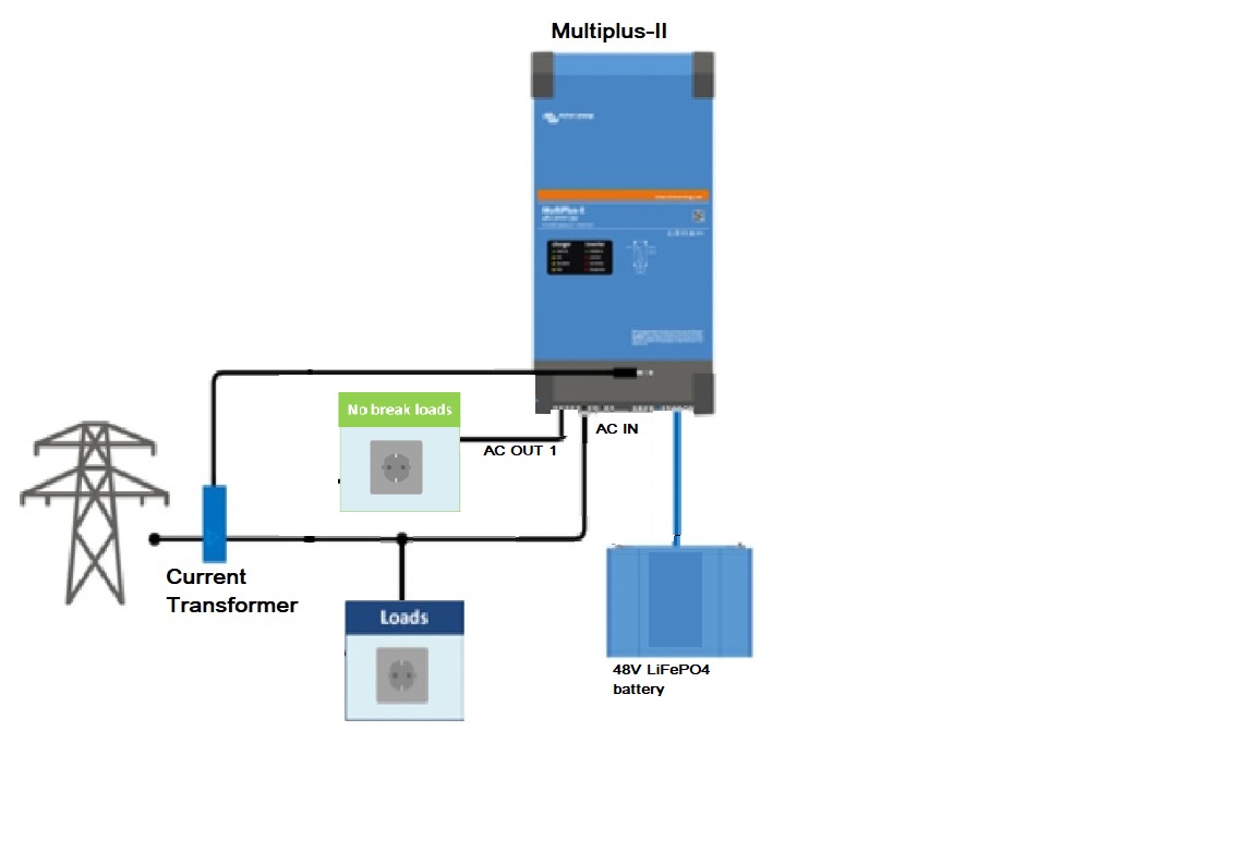
Below is the diagram of my setup:

configuration-diagram.jpg

configuration-diagram.jpg

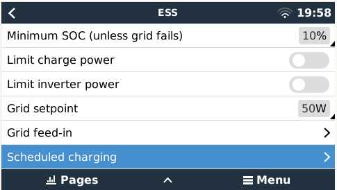
In VEConfig, I have the following settings:


TAB: General

System frequency 50Hz

Shore current 100.0 A

Overruled by remote unchecked

Dynamic current limiter unchecked

External current sensor connected (see manual) checked

State of charge when Bulk finished 90.0 %

Battery capacity 277 Ah

Charge efficiency 0.95

TAB: Grid

Country / grid code standard UK: G98/1 March 2019, G99/1 May 2018

LOM detection AC input 1 Type B (grid code compliant)

start P(f) at 50.40 Hz

start delay for p(F) 0.08 s

Droop for p(F) 10.0 %

Use Aux1 (if available) as disable FeedIn signal checked

Reactive power regulation Use a fixed Cos Phi

Filter time for reactive power 3.3 s

Cos phi at point 1 1.00

TAB: Inverter

PowerAssist unchecked

Inverter output voltage 230 V

Inverter DC shut-down voltage 48.00 V

Inverter DC restart voltage 50.00 V

Low DC alarm level 49.00 V

Do not restart after short-circuit (VDE 2510-2 safety) unchecked

enable AES unchecked

TAB: Charger

Enable charger checked

Weak AC input unchecked

Stop after excessive bulk checked

Lithium batteries checked

Configured for VE.Bus BMS unchecked

Charge curve Fixed

Absorption voltage 55.00 V

Float voltage 52.00 V

Charge current 70 A

Repeated absorption time 1.00 Hr

Repeated absorption interval 7.00 Days

Absorption time 1 Hr

TAB: Virtual switch

TAB: Usage

Virtual switch usage Do not use VS

TAB: Assistants

TAB: Assistant Configuration

ESS (Energy Storage System) (size:962)

*) System uses LiFePo4 with other type BMS

(This can be either a BMS connected via CAN bus or a BMS system in which the

batteries are protected from high/low cell voltages by external equipment.)

*) The battery capacity of the system is 277 Ah.

*) Sustain voltage 49.00 V.

*) Cut off voltage for a discharge current of:

0.005 C= 48.00 V

0.25 C= 48.00 V

0.7 C= 48.00 V

2 C= 48.00 V

*) Inverting is allowed again when voltage rises 2.00 V above cut-off(0).

*) Relevant VEConfigure settings:

- Battery capacity 277 Ah.

- PowerAssist unchecked

- Lithium batteries checked

- Dynamic current limiter unchecked

- Storage mode unchecked

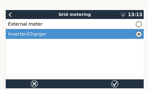
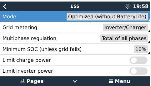
In VenusOS - ESS, I have the following settings:


ess-p1.jpg

ess-p2.jpg

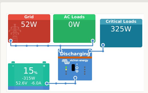
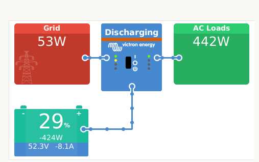
From the VenusOS screen shown below, it seems that the ESS system was working properly as per my expectation that:

  1. Discharge the battery to supply the loads of the house
  2. The grid setpoint was kept at around 50W

venusos-screen.jpg

However, I have the following queries (or encountered some problems):

  1. While the VenusOS screen showed that the grid setpoint was kept at around 50W, a clamp ammeter at the CT point location showed that the grid was supplying 2.3A (i.e. around 520W) to the house at the same moment. That was 10 times larger than the grid setpoint. When the house asked for more load, the grid setpoint in the VenusOS screen still showed 50W and the clamp ammeter also showed around 2.3A. It seems that ESS thought that it was keeping the grid setpoint at 50W but in fact the power supplied from the grid was much more than that. What was causing such discrepancy? (Note: The chance of a faulty CT is low because I tried 2 CTs. Both had the same result.)
  2. Before the turning on of the MP-II, the clamp ammeter showed that the house was drawing 2.7A from the grid. After the MP-II was turned on, ESS then worked as shown in the above VenusOS screen. In that screen, you can see that the battery was giving 424W. The grid was giving (from the clamp ammeter) 2.3A or 529W at the same moment and therefore the total was 424 + 529 = 952W. However, before the turning on of the MP-II, the house was only using 2.7A or 621W. There was a more than 300W differences. Did it mean that the MP-II was itself eating up 300W? Or, such confusing figures were also caused by the cause of problem 1 above?
  3. In the VenusOS screen, only one “AC Load” was shown. I got that the "AC Load" shown also included the load connected to AC-Out1 (i.e. the critical load). Is it possible to show the load at AC-Out1 in a separated box? If yes, how?

Thank you very much in advance for any help/advice.

ESS
ess-p1.jpg (19.0 KiB)
ess-p2.jpg (16.4 KiB)
venusos-screen.jpg (12.7 KiB)
5 comments
2 |3000

Up to 8 attachments (including images) can be used with a maximum of 190.8 MiB each and 286.6 MiB total.

d3-energy avatar image d3-energy commented ·

Keep in mind that you don't necessarily use cheaper energy this way during peak hours.
At my electricity supplier, the difference between peak and off-peak tariffs is not that great.
After all, the current that the Multiplus takes from the battery is converted 2x (AC -> DC and DC -> AC) with a small loss and your Multiplus also has its own consumption.
But at least it's educational. Good luck!

0 Likes 0 ·
elel avatar image elel d3-energy commented ·

Thanks for the comment. I am lucky that my supplier charges 1/3 of the peak price for 4 hours after mid-night (and hope that such special electricity plan lasts long). I am aware of the losses due to AC->DC, DC->AC and battery storage and my gut feeling is that the total losses would not be more than 25% so, depending on how deep I charge/discharge my battery pack, it would still be a worthwhile investment with a payback period of around 7 to 8 years. However, this is just a calculation on paper and I still need a proof of this concept by getting the actual losses during the process and that is why I am keen on knowing why the grid setpoint does not agree with the actual current drawn from the grid (i.e. my question 1) and why it seems that the MP-II is eating up (or losting) a lot of power (i.e. my question 2).

0 Likes 0 ·
d3-energy avatar image d3-energy elel commented ·

I myself am still learning every day. So my answer might be wrong.

But if I look at your info, in the ESS menu you have chosen the value 'inverter/charger' under the option 'grid metering'. I think ESS uses this point (AC IN) to set the value of 50 W (which it works well).

Can you choose your second meter there (current transformer)?

If I remember correctly (not near my setup right now) it will notice a difference between both meters (CT and AC-IN) and then it displays this with an extra box AC loads (between grid and Multiplus).

0 Likes 0 ·
elel avatar image elel d3-energy commented ·

Thanks for your input.

It is in fact very confusing (with very limited information from the manual) when I was trying to find how I can tell ESS to use CT to check the grid import/export. Here are the two options in ESS:

p2.jpg

I believe the "External meter" option is for the Energy Meter ET112 but I am using CT. The most possible choice is therefore "Inverter/Charger" as I have selected "External current sensor connected" in VEConfig and this causes MP-II to use the external CT instead of the internal one.


I did try selecting the "External meter" option and here was the VenusOS screen:

p1.jpg

The problem (i,e. having around 2.3A supply from the grid while the grid setpoint was shown as 50W) was still there but with a even confusing display in VenusOS. You can see from the screen that all the house loading (which should be shown in the "AC Loads" box) was put into the box "Critical Loads" which does not make sense.

0 Likes 0 ·
p2.jpg (19.1 KiB)
p1.jpg (29.4 KiB)
d3-energy avatar image d3-energy elel commented ·

I had hoped that the difference in measured amps would be shown in the new (green) box. Sorry, but I'm afraid I can't help you further. Kind regards.

0 Likes 0 ·
5 Answers
Paul B avatar image
Paul B answered ·

This maybe of help and it maybe leading you down the wrong path - but its a easy solution and worth a try.


I have this week seen a notice from victron that says.

on a multi plus II there is a hard ware fault (maybe) in the small round AC current meter plug. they think that there maybe a bad connection when the plug is NOT being used. and thus causing incorrect amp readings.

Current recommendation is is to insert a plug into that connection a few times (in and out) and this clears the bad connection .

Below is the info plus a cop of the PDF 2021-12 MPII-ESII-QUAII Current Sense Socket Issue - rev3.pdf


Dear Customer,


This email is to inform you that the some MultiPlus-IIs, as well as EasySolar-IIs and Quattro-IIs can have an issue with their AC input current measurement. This is due to a contact issue in the AC Current Sense socket input – and affects the most common use case: systems where the optional external Current Sensor is not installed.


The problem does not occur often, but is hard to recognise in case you are not aware of the possibility. And it is simple to solve, once you know how to solve it.


Details in attachment.


Note that we are still investigating the issue further, and will share more information when available.


For further questions, please contact your sales manager.


Yours sincerely,


Matthijs Vader

Victron Energy BV


2 |3000

Up to 8 attachments (including images) can be used with a maximum of 190.8 MiB each and 286.6 MiB total.

bobbyb avatar image
bobbyb answered ·

Hi did you ever get to the bottom of this problem ? - I am having the identical problem as this where it is constantly pulling 160 watt off the grid even tho the grid point is set to 50 watts ?

NB mine is latest multiplus 2 with the update connection for the CT (which is just linked out) as i am not using an external CT

Any would be much apricated

Bob

2 |3000

Up to 8 attachments (including images) can be used with a maximum of 190.8 MiB each and 286.6 MiB total.

cathal-h avatar image
cathal-h answered ·

Apologies in advance for pulling up old thread. but I've exact same issue.

200 watts being pulled from grid (verified with external hand help clamp meter) when ESS is saying 'zero'. I'm running MultiPlus -II / ET112 / all firmware up to date as of today.


Thanks

2 |3000

Up to 8 attachments (including images) can be used with a maximum of 190.8 MiB each and 286.6 MiB total.

kevin-cahoon avatar image
kevin-cahoon answered ·

Mine is doing something similar, measuring the amount transferred to AC loads on the Shore Power, but over 1000w chagaring the batteries, is not showing up coming from Shore power

2 |3000

Up to 8 attachments (including images) can be used with a maximum of 190.8 MiB each and 286.6 MiB total.

joker-sk avatar image
joker-sk answered ·

Well that discrepancy can be (and im no electrician) that "the energy is not used"?

something along the PowerFactor being low, because the multi is just being connected and "fighting" with the grid and/or internal invertor to keep that 50W.

I saw something similar, that the multi was showing 50W, yet something around 1,5A, and shelly powermeter was showing also something like 50W, but with PF of 0.2

Hopefully im not wrong, but the powemeters "should" account you for the "used watts " so factoring this PowerFactor in

Or?

2 |3000

Up to 8 attachments (including images) can be used with a maximum of 190.8 MiB each and 286.6 MiB total.