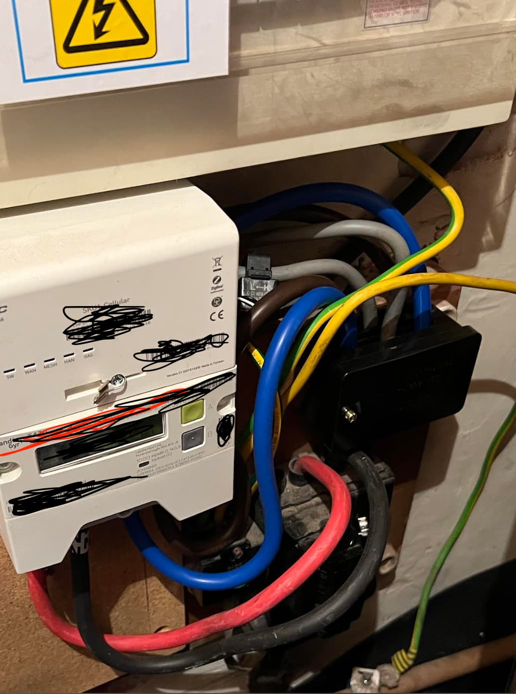
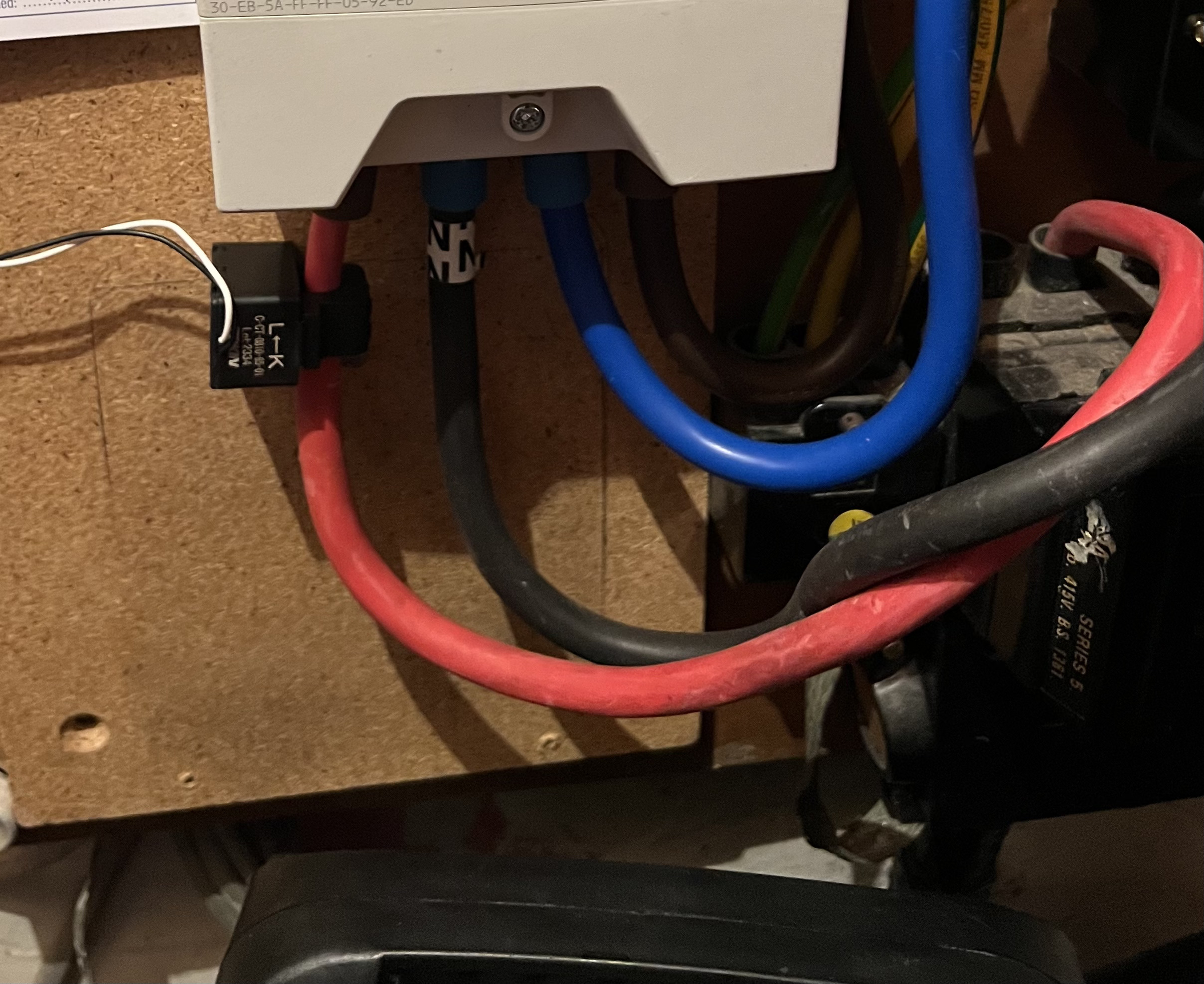
Where is the CT has to be installed?
The live wire going into the meter is too thick for the clamp that comes with Victron Energy Meter VM-3P75CT.
what other option do I have other than going for another Victron Energy Meter ( ET112)?

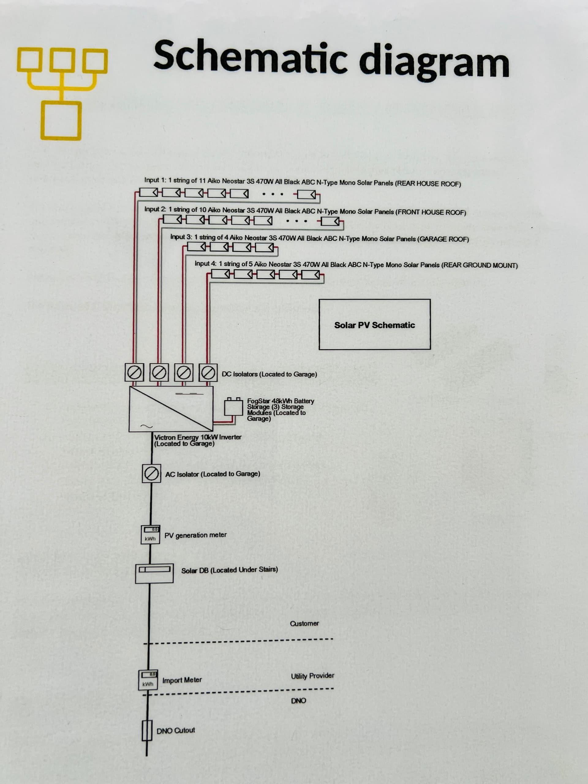
I need to either locate the system schematics or create one myself. My installer is currently working with a technician from Bimble Solar to resolve the issue I’m experiencing. At the moment, the system seems to be constantly charging the batteries while the AC loads are always drawing power from the grid, both during the day and at night.
The inverter is currently set to “ON” mode, and the ESS is configured to “Optimized with Battery.”
The likely cause appears to be the CT clamp, which may have been installed on the wrong wire.


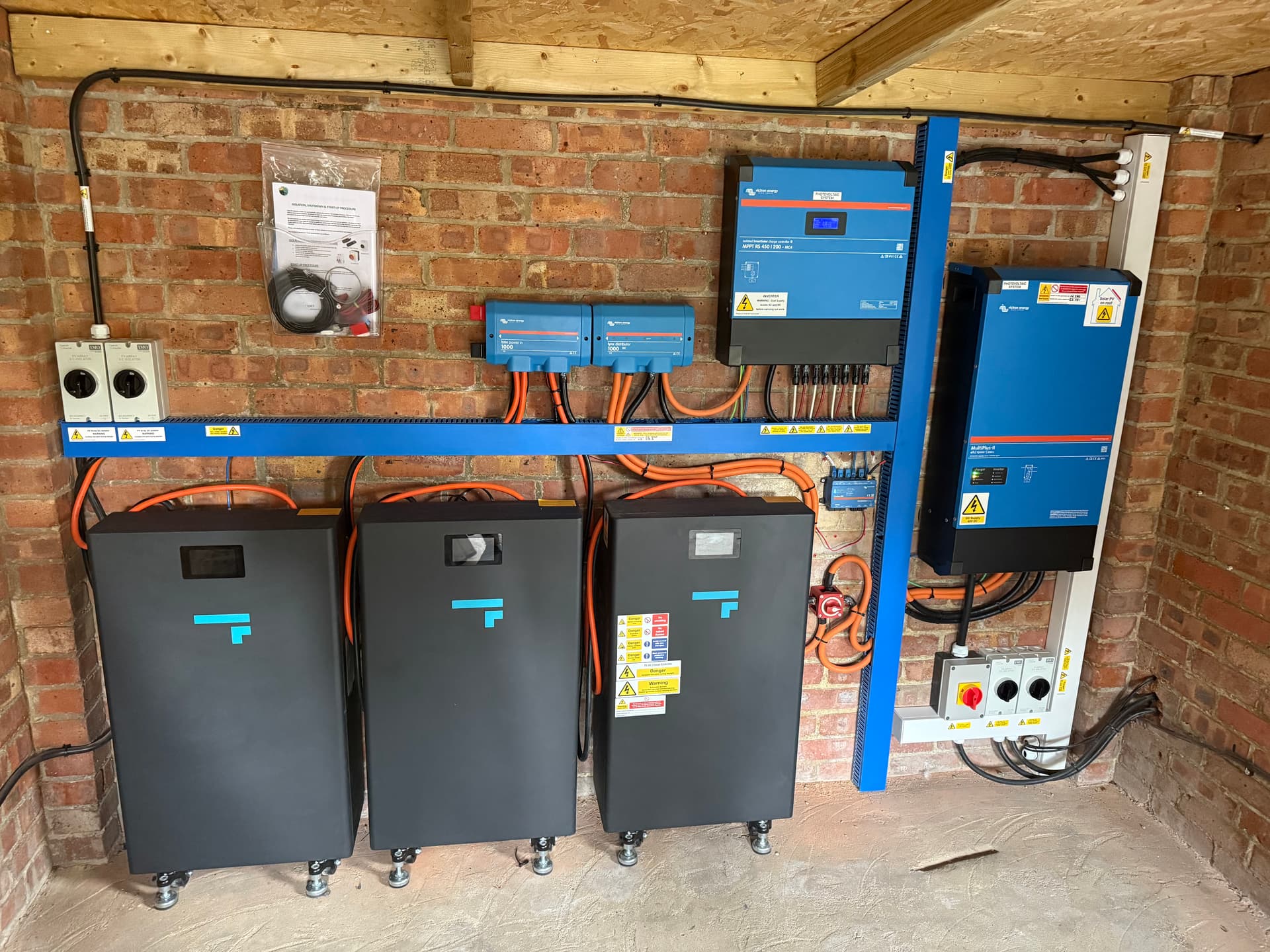
Optimism without battery life should be selected, How doe the multi cover the load is it just back feeding through AC in and no AC outs used?
In which case you will need a clamp at the meter. Someone must have schematics, as it’s hard to position where the multi is in the install to me it doesn’t look like everything is routed through the multi as the Henley block is the first thing from the meter meaning somethings will be before the multi, just from what it looks like in the pitcure.
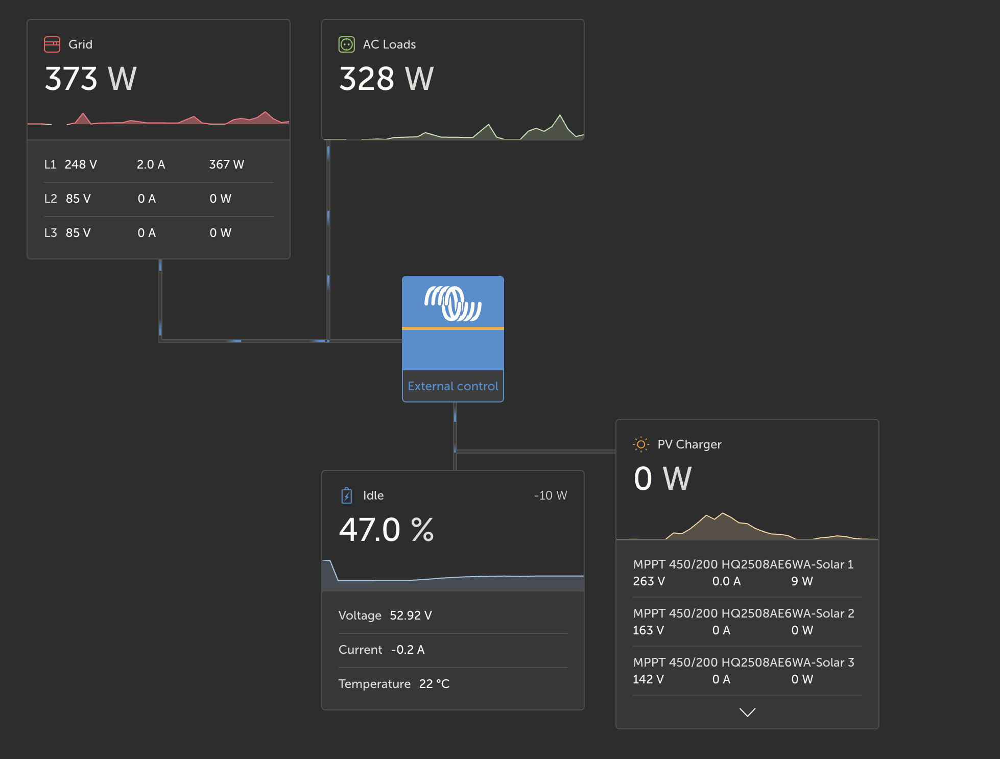
From the VRM it does look like AC in is used meaning you need a clamp at the meter ie an where before the Henley blocks


I’m using everything through my multi ie just AC out so I use the multi to do the current stuff, if you are using a CT external should be your selection.
Also specifi the position of the load to be covered. Hope that helps but I fear your not going to be able to rectify without a CT the way it looks like it has been setup.
EDIT I’ve just seen where the CT is and it is in the wrong place only the brown or the red will cover all the loads so yes it’s in the wrong place if you want to cover all the loads but again if it’s 25mm2 that VM-3P75CT won’t fit over the double insulated cable
The clamp was just repositioned, but the system is still behaving the same. According to the installer, the issue might be due to the street voltage, which is unusually high, around 251V. This could be triggering the Victron inverter to default into charging mode as a protective response or its a software issue.
High voltages will trigger grid rejection once the grid code parameters are exceeded.
What! 415v Contact your DNO that voltage is going to fry stuff! That’s not unusual that’s broken. I take it your installer has tested the grid connection with the system disabled to get that grid voltage?
If not that’s what needs to happen just to rule out the system from DNO’s side. The DNO will do similar when they come out.
Tell the installer check for a broken neutral or to see if it’s using the earth in which case be careful of the metal pipes. Just something to rule out is the earth and neutral. Hope you get this sorted as not the clamp is in the right place
Sorry, I meant 253v.
The DNO has already conducted their checks and confirmed that the incoming voltage is 243V. They also stated that their equipment is more accurate than others, so the issue is not related to street voltage.
The problem remains unresolved, no one can explain why the AC loads are not drawing power from either the solar panels or the battery.
Dam was thinking everything in your house should have been fried lol, normally the DNO’s equipment is left at the customer’s address for a week at least that’s what UK power Networks have done.
I went through this myself I would disable the system and read the voltage. Yes there tools are calibrated but it should be used at the address the fault is at and the equipment normally left in place for a week and all solar generation equipment should be disabled in order to work out if it’s a grid thing or your power end.
Seems pretty quick to reach the conclusion that it’s your end taking into account that solar everywhere that feeds back to that transformer is out of its peak now which could affect the voltage if on the same line as you.
Have you changed the setting to cover the AC in load?
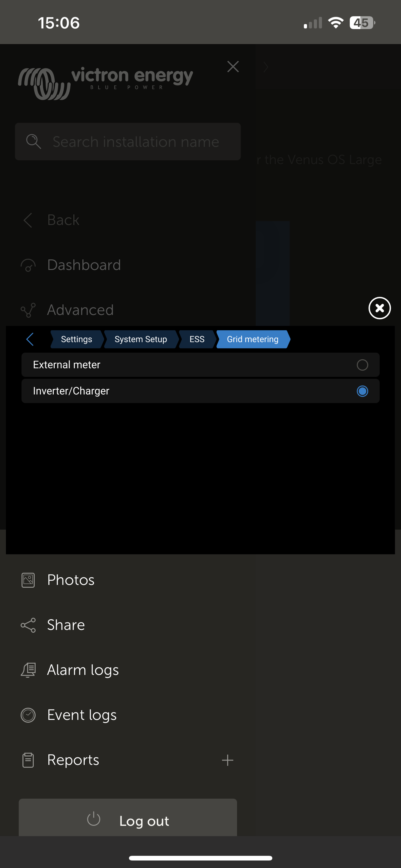
@saad1200 Also ensure the energy meter is configured for the correct number of phases and role etc.


I assume this installer doesn’t install much Victron gear then!? ![]()
This was his first time installing the system. It wasn’t easy to find an installer willing to take on the job. It was a steep learning curve for him, and I’m not sure he’d be open to taking on another Victron project ![]()
That’s understandable then. Like you say, it’s a steep learning curve. The Victron stuff is very configurable but it does take some getting your head around. I’m in the UK and there’s not many Installers for it over here. They tend to stick to the likes of Solar Edge and Tesla who have a very locked down ecosystem. The home owner has very little they can adjust on those systems which is probably a good thing where most of the non-technical folks are concerned.
As an electrical engineer, I wanted a DIY system that I could fully customise and then take with me if I moved house! ![]()