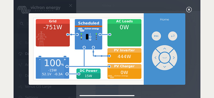
I had a moment, and remembered that sometimes the Multiplus-II considers AC out to be what I regard as AC in. And so I wondered if it applied here.
That triggered me to think about where the grid CT is. And, of course, there is an in-built one, and also the option to move it external. So I wondered if it was all about the relative position of the two CTs, with the assumption that “on AC input” actually means “on the grid-side of the grid CT”. Of course, when the grid CT is internal, that is naturally achieved by placing the AC current sensor CT on the input side.
Anyway. It seems to be working. I re-configured the MultiPlus-II to think the AC current sensor is on the AC output, and numbers look better. It is still in it’s first 24-hours so the zero has not calibrated yet. I’ll report back again once it has.
However, having done that, I was reading more closely the ESS manual, and it has muddied the waters rather. It says:
“With and without grid-meter”
“Where there is no grid meter; all loads are connected to AC-out. And where there is a PV Inverter present that is also connected to AC out.”
So that confuses things as I’d been running ESS for some time without PV Inverter, and with loads on AC in.
“Grid Meter (optional)”
“input side”
“If there is any AC renewable energy source or any AC load between the grid connection point and the input side of the Multi/Quattro system, incorrect results will be calculated and recorded by the GX unless a grid meter is installed and enabled.”
“In particular, without a grid meter:”
“• When renewable energy is being provided on the input side, the grid value will be wrong (too low/negative); and”
“• The AC Load value shown will be too low (and will show zero where there is a surplus of renewable energy).”
“Both issues are resolved by installing a grid meter.”
So that at least matches and provides an ‘official’ explanation of my symptoms, together with a potential answer. It also seems to conflict slightly with what it said earlier. Anyway, when I have a bit more time, I may go and look at a more recent version of the ESS manual and see if it has been clarified in the meantime.
Anyway. Thought it might be useful in case someone else walks this path.


