Low Battery Voltage Error on MultiPlus-II 10000/140 with Dyness DL5.0C Batteries (with Heating)

Hello everyone,

I’m experiencing an issue with my setup and would appreciate some guidance or if anyone else has seen this before.

System setup:

  • Victron MultiPlus-II 10000/140

  • 2x Dyness DL5.0C batteries (with heating)

  • ESS enabled

  • DVCC configured

Problem:

The inverter reports Low Battery Voltage (red alarm), but as you can see from the attached graph, the battery voltage does not actually drop that low. Right after this error appears, the power cuts out and I need to wait for the inverter to come back online.

At the same time, I also see Overload L1 and High DC Ripple warnings.

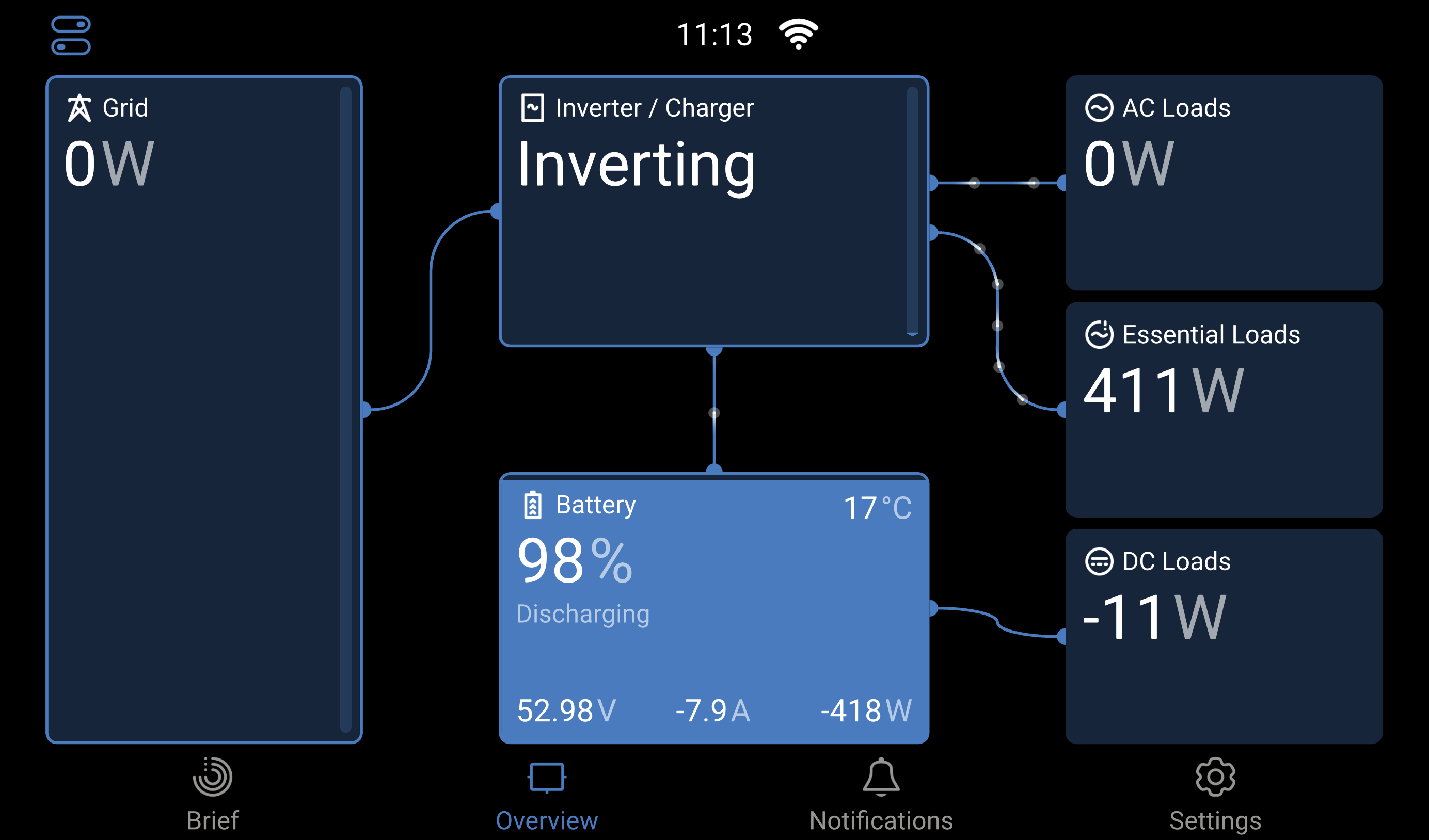
Here is a snapshot from VRM this morning (see image):

  • Voltage remained steady around 53–54 V.

  • Current shows some spikes (positive and negative).

  • At 10:58 the system was at 53.67 V and 19.1 A when the error occurred.

Questions:

  1. Could this be caused by ESS/DVCC misconfiguration with the Dyness batteries?

  2. Is this a communication issue between the MultiPlus and the BMS, since the BMS data doesn’t seem to match what the inverter reports?

  3. Could high DC ripple or current spikes be falsely triggering the low-voltage cutoff?

  4. Has anyone with Dyness DL5.0C batteries (with heating) seen similar cutoff behavior?

Any advice, configuration tips, or troubleshooting steps would be greatly appreciated. I’m trying to determine if this is a settings issue, a wiring/cable sizing problem, or something related to BMS integration.

Thanks in advance for your help!


Update:

I also noticed another strange behavior — even though the system is connected to the grid, it does not draw any power from the grid.

From the screenshots attached, you can see:

  • The inverter is in Inverting mode, showing battery discharging (around 98% SOC, 53 V, –8 A).

  • AC Loads show 0 W on the main side, with only ~408 W shown under Essential Loads.

  • The Grid meter is active and reporting (228 V, 0.5 A, 1 W), but the inverter is not actually pulling power from it.

This makes me wonder if ESS or DVCC settings are interfering with the grid import logic, or if there’s a configuration mismatch (e.g., input current limit, ESS mode, grid setpoints).

Has anyone seen a case where the MultiPlus-II stays on battery even though grid is available and loads could be covered by AC input?

Any tips on what settings I should check (ESS mode, grid setpoint, AC input current limit, priority settings) would be really helpful.

What are the values from “Dynamic cut-off“ (VE Congure)

They were 47V for each option as i saw on another post, but i never got an answer as to why.

2h ago i did this setup: https://www.pvpower.co.za/wp-content/uploads/2022/10/BMS-Setup-Victron-INSTALLATION-MANUAL-VICTRON-and-DYNESS_V2-1.pdf

And it is stable so far, but i might need some knowledge sharing on the Dynamic cut-off values, what do they mean? now they are set to 46V

I am posting the full export.

TAB: General

System frequency 50Hz

Shore current 40.0 A

Overruled by remote checked

Dynamic current limiter unchecked

External current sensor connected (see manual) unchecked

State of charge when Bulk finished 95.0 %

Battery capacity 200 Ah

Charge efficiency 0.95

TAB: Grid

Country / grid code standard Other: not compliant to any grid code standard

AC input 1 Above selected gridcode plus LOM B (safe)

Accept wide input frequency range (45-65 Hz) checked

AC low switch mains off 187 V

AC low switch mains on 190 V

AC high switch mains on 260 V

AC high switch mains off 265 V

UPS function checked

TAB: Inverter

PowerAssist unchecked

Inverter output voltage 230 V

Inverter DC shut-down voltage 46.00 V

Inverter DC restart voltage 48.00 V

Low DC alarm level 48.00 V

Do not restart after short-circuit (VDE 2510-2 safety) unchecked

enable AES unchecked

TAB: Charger

Enable charger checked

Weak AC input checked

Stop after excessive bulk unchecked

Lithium batteries checked

Disable VSense (for diagnostic purposes) unchecked

Configured for VE.Bus BMS unchecked

Charge curve Fixed

Absorption voltage 52.00 V

Float voltage 51.00 V

Charge current 100 A

Repeated absorption time 1.00 Hr

Repeated absorption interval 7.00 Days

Absorption time 1 Hr

TAB: Virtual switch

TAB: Usage

Virtual switch usage Do not use VS

TAB: Assistants

TAB: Assistant Configuration

ESS (Energy Storage System) (size:1031)

*) System uses LiFePo4 with other type BMS

(This can be either a BMS connected via CAN bus (e.g. a Lynx Smart BMS) or a

BMS system in which the batteries are protected from high/low cell voltages by

external equipment.)

*) The battery capacity of the system is 200 Ah.

*) Sustain voltage 49.00 V.

*) Cut off voltage for a discharge current of:

0.005 C= 46.00 V

0.25 C= 46.00 V

0.7 C= 46.00 V

2 C= 46.00 V

*) Inverting is allowed again when voltage rises 1.20 V above cut-off(0).

*) Relevant VEConfigure settings:

  -  Battery capacity 200 Ah.

  -  PowerAssist unchecked

  -  Lithium batteries checked

  -  Dynamic current limiter unchecked

  -  Storage mode unchecked

Total size of all assistants including the required

(hidden) system assistants is: 1090

TAB: Advanced

limit internal charger to prioritize other energy sources unchecked


Here i have a sample of no power for today.


And one example of Low Bttery error

I use for trouble shouting a export of a xls or csv download

Is this a new installation?

CJDezmir_log_20251004-1900_to_20251005-1819.xlsx.zip (294.4 KB)

Is this good?

Yes it is a new instalation, my first one, 30 days old, been having issues since then, i tried multiple configurations.

Perhaps try and check all connections, its a start and from there you can dive in to configs. Make sure the connections are all doing fine, even if you think the are doing fine, checking them is always good to do. Communication cables, DC connections and so on.

Already did that 3 times, checked the torque, checked the comm cables. Everything.

Since yesterday i got only one occurance where the Output Voltage dropped to 0.

which coincides with this:

I see no battery in the log file (are they connected?)

And I see a lot of Grid lost? are you off grid

Voltage looks Ok but there is High DC rimple (what cable are you using mm2/long)

Im am not off-grid, sometimes the city grid fails in my area, thats why i got this setup, to store some energy for 20h.

Now for the cables, i used the original cables belonging to the batteries, they are 25mm2 and 1.8m long. I saw the DC ripple too. I already prepared a 60VDC capacitor 100.000uF for dc ripple compensation. But i didn’t install it yet.

I am planning to replace the cables too, with thicker ones. At least 50mm2 for each battery and shorter, i don’t need 1.8m

Status update:

it’s been almost 30h since i did the following changes to the system and i did not had any low battery voltage alarms, nor output voltage drops.

  1. I replaced the battery cables to 50mm2 for both batteries.
  2. I removed the VICTRON ENERGY - Current Transformer 100A:50mA for MultiPlus-II (1m) VICCTR110000500. I had it connected even though i did not used it. Since i installed an ET112. It was disabled in the config of multiplus.

At this point i am not sure which one is the factor which affected my functionality. I am still monitoring it. And will close this thread in 4 days if no alarms or output drops manifest.

@bolchisb

I assume the CT clamp was responsible for not connecting to grid.
The underrated DC cables are are responsible for DC ripple.
How do you connect your batteries and MP2 exactly. Do you have a Lynx in between? Do you have fuses?
I have 1x 70qmm per MP2 5K. I have three MP2s, e.g 210qmm for 15kVA.
I have 4x 15kWh batteries. Each connected via 50qmm to the Lynx, though 200qmm on battery side.
I experienced 1V voltage difference between MP2 and BMS under load. I attached a voltage sensing line from MP2 to battery. Now I can use full rated power of MP2.

The batteries are connected to the MP2 directly with cables. And a fuse of course, i do not have a lynx since i use the battery bms. Do i need one?

Regarding the 25mm2 cables, i used the original cables delivered with the batteries, and they asured me they are correct. But still i decided to use thicker cables and double the section of them

@bolchisb
My first battery pack came with 35qmm silicon cables. Later once have been upgraded to 50qmm after complaints from community and famous YouTubers like Andy from OffgridGarage.

I have a Lynx Distributor as DC bus bar in between batteries and MP2s. The name Lynx is used for a range of Victron products only one being a BMS.

See my build thread about more details one fuse monitoring and alerting.

2 Likes

This topic was automatically closed 14 days after the last reply. New replies are no longer allowed.