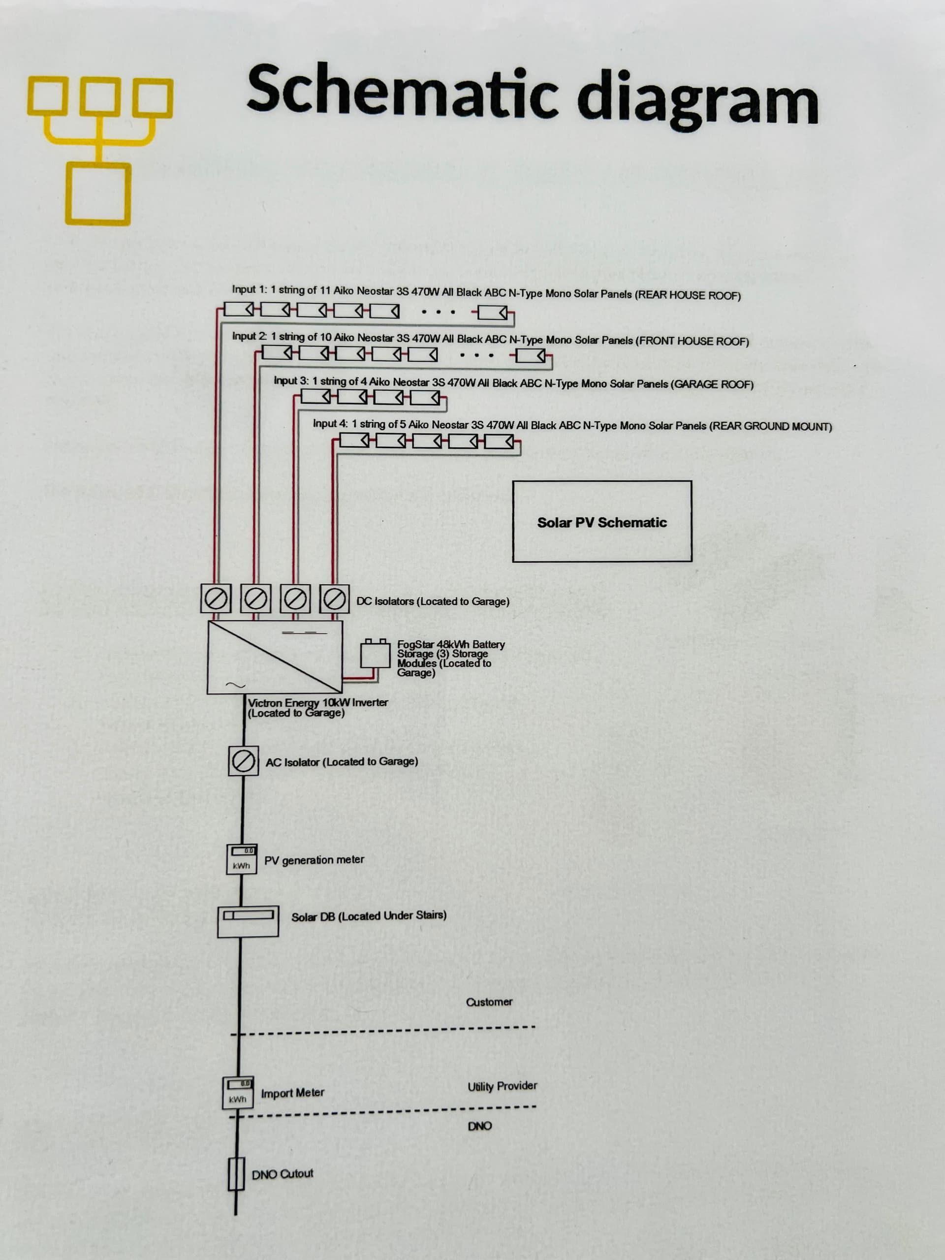
In my Victron system schematic, there is a Solar DB (Solar Distribution Board). Recently I’ve noticed that the fuse/breaker inside the Solar DB keeps turning off quite often.
Is this expected behavior, or does it point to a wiring/installation issue? How to troubleshoot to identify the root cause?
Some details about my system:
Solar PV:
South-facing: 10 × 470W = 4.7 kW
North-facing: 11 × 470W = 5.17 kW
West-facing: 9 × 470W = 4.23 kW
Inverter & Export:
Victron inverter size: 12 kW
DNO export limit: 12 kW
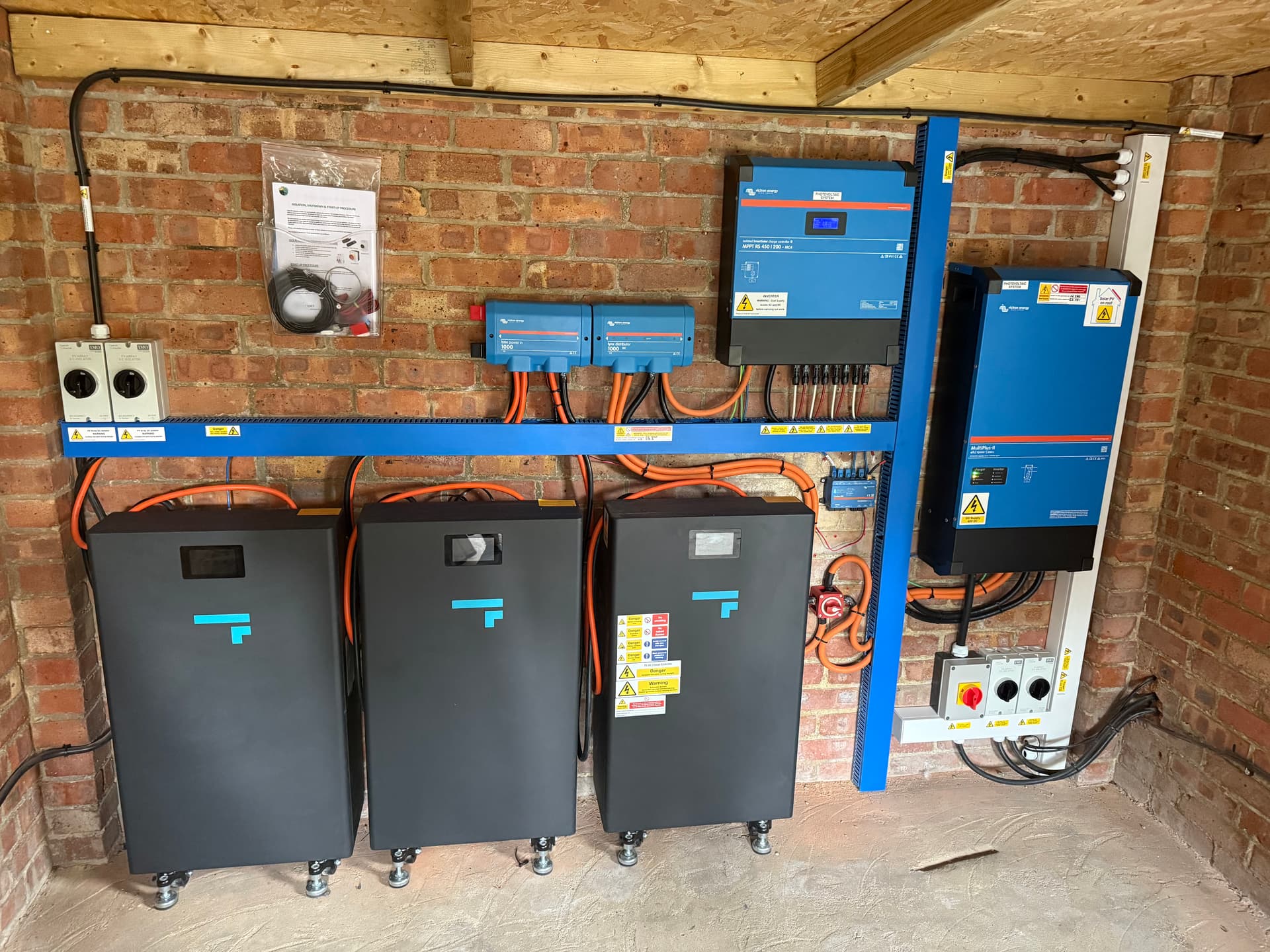
Battery capacity: 3 × 15 kWh = 45 kWh
Home consumption:
Annual usage: 4100 kWh
Inverter: Victron MultiPlus-II 15000V
Fuse/MCB size in Solar DB: [insert rating if known]
I take it your on RCBO’s? When does it trip, I had to change my solar back to MCB as in the event that the grid went down and then came back the solar RCBO’s would trip, solar stuff I find very leaky where it comes to earth and that just sets off the RCBO and if this isn’t a bi directional RCBO that’s when the issues of the live being switched but the internal chip still getting power and just burning out.
Make sure it’s bi directional if your going RCBO route maybe consult a spark to get the once over, what is your earthing arrangement?
I would say get a spark to measure the earth current leakage from the PV inverter, I take it it’s the a PV inverter rather than the multiplus that you are referring too? Either way if it’s not over current, my opinion is an earth leak which is going to be a pain as it’s not consistent. Try to see if it does it when it rains different times of the day you need to note it in order to help the spark and save yourself money not having to call them out again because the problem didn’t present at the time.
I’m using an RCBO, and I don’t believe it’s bi-directional. it’s the breaker for the PV inverter. I’m still not sure why the trips are happening, but I suspect it occurs sometimes in the middle of a sunny day. As you mentioned, it’s not consistent. I’ve informed my installer, but I’ll continue monitoring and noting when it happens. I’ll share updates on this thread.
Who done the sizing for that RCBO? Also make sure the RCBO is bi directional and ask the spark to confirm that’s as an amendment was rushed through to correct a potential safety/fire issue risk see 18th Edition Amendment Regulation 530.3.201 and see EFIXX video so you know and the spark knows how big is your AC PV inverter kW wise and the Array connecting to the AC PV Inverter? Link to EFIXX https://youtu.be/MnaNILKlx8M?si=EgAE101O63xrJku3
Not sure but the schematic diagram is showing 10k inverter instead of 12k. This makes me think its the Victron sales advisor/engineer at bimblesolar
RCBO is bi directional
This has been confirmed.
what is the earthing arrangement?
Arrangement: TNC-S (Protective Multiple Earth), often referred to as PME.
This is what I am planing to replace to fix this issue:
Component / Action
Current Status
Requested Upgrade/Action
Reason for Action
Inverter DC Fuse
Installed, but recommended to be 500A (Must be checked against current rating)
Upgrade to 500A Mega Fuse (e.g., Victron CIP138500020, 80V rated)
CRITICAL SAFETY. Protects the high-power 15kVA inverter from catastrophic short circuits from the battery bank. Victron mandates 500A-600A fusing for this inverter size.
Master DC Disconnect Switch
NEVER installed.
INSTALL 600A DC Isolator (e.g., BEP 720 or Blue Sea HD 3000)
CRITICAL SAFETY. Provides a highly rated, manual safety isolation point capable of handling the entire system’s 400A continuous current.
RCBO
B50 RCBO
Replace the B50 RCBO with a B63 RCBO
Improve reliability by eliminating nuisance tripping caused by the 50A limit and thermal derating, and to enable the full charging rate (up to 60A from the grid for faster battery charging).
Mate I’ve had a couple of sleeps since this I’ve forgotten everything
That PV fuse doesn’t make clear what who it belongs to ie that Victron Solar inverter or the multiplus?
With that earthing arrangement you need an earth rod and supplementary earth bonding applied ie earth rod and measurements taken to ensure it’s working efficiently.
As regards to switches on positive supply I got rid of mine two may people reporting burn outs so decided to ditch it and use the BMS just to switch it off, been watching a guy on YouTube trying to blow the fuses even the mega via short circuiting the battery but the BMS on the EG4 was tripping before the fuse got chance to even think of blowing.
But if you are set on a switch maybe get the blade type fuse disconnects and illuminate the switch, you have a lot more space than me which was also a reason why I just went with the Lynx distro
The small 250A fuse you’re seeing is for the Victron MPPT solar charger (the PV side).
I just realised my Lynx has two 300A fuses protecting the MultiPlus-II 15kVA inverter. With a combined rating of 600A, the fusing is correctly sized and matches Victron’s top recommended specification for that inverter.
Yeah, I might ditch the switch too. If the system’s working, I don’t want to mess with it. The only thing I need to sort is that 50A breaker upgrade.
I would be careful with this switch as it’s these that tend to get hot, also check to see if there is an earth rod as if your grid goes down on a TNC-S earth arrangement then the earth goes as well which would create problems with devices not tripping
yes I believe so. That is the breaker for the multi.
By the way, I’ve opened another topic to understand whether upgrading the B50 to a B63 is a reasonable request in order to increase AC charging. I’m curious if others have run into the same limitation or if it’s just me. I also don’t really understand why a B50 was installed in the first place.
Yeah I upped mine to 63amps as it’s 100amp capable but worked out that total demand would never be that high so set the multi in limit to 63a. It could be that they deemed your total demand to be too high, I would contact the system designer to see what the rational was.