Hello,
Seeking help regarding state of charge discrepancy with a Victron Smart shunt.
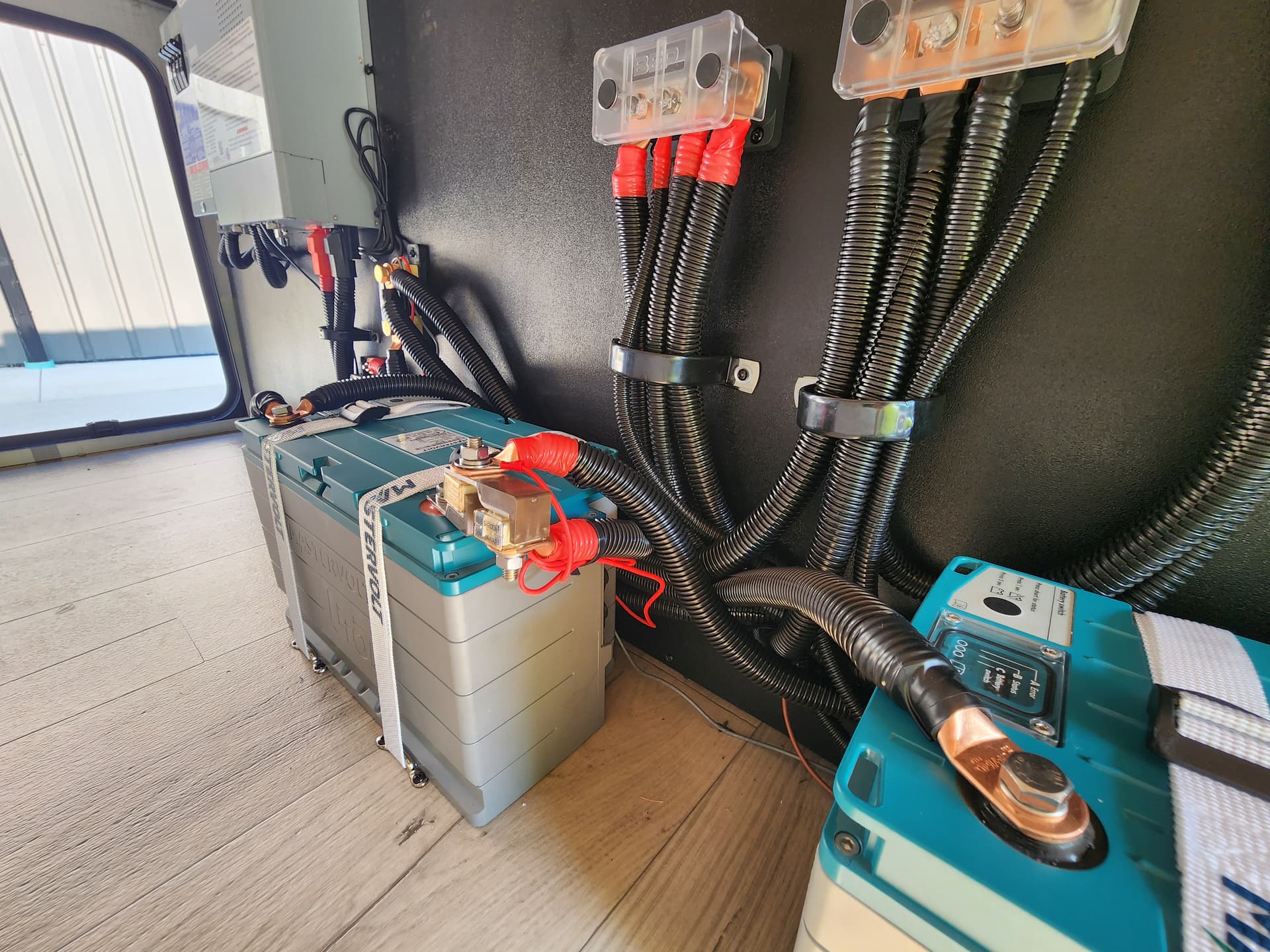
I have a customer with a Rockwood Ultralite 2618RD that we installed a 200Ah Lithium battery system that has a Victron Smart Shunt (500A) monitor.
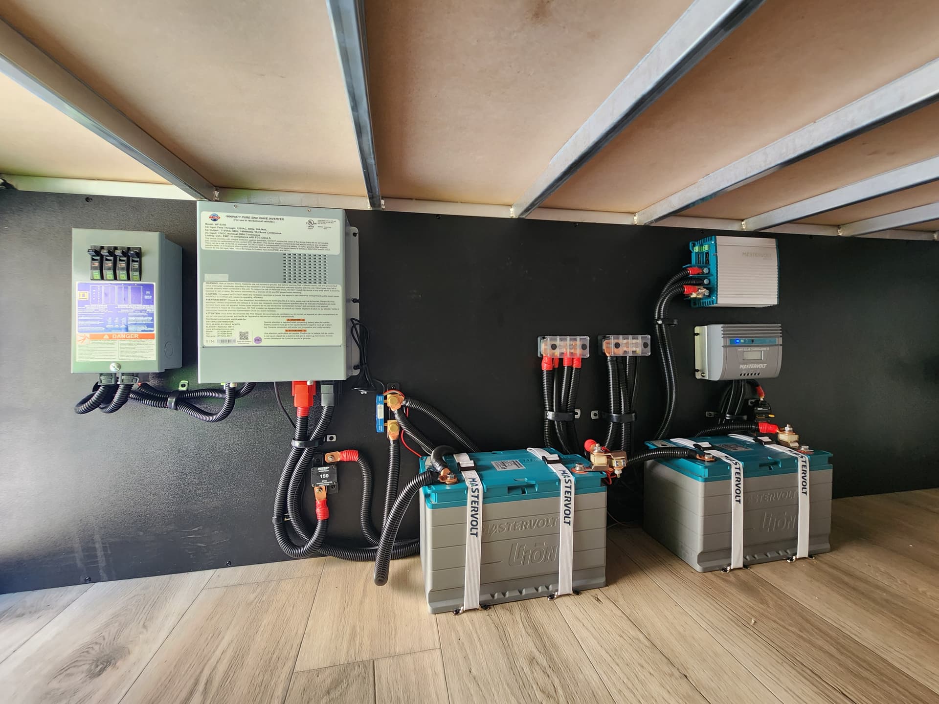
The main components of the system are the following: 2 Mastervolt MLI1250 100Ah batteries, WFCO 98 series deck mount converter charger, WFCO WF-5318 Auto Detect 1800w inverter. Mastervolt 50A DC/DC charger, Mastervolt 25A MPPT solar charger
He is getting a wide variance in state of charge from the shunt vs the internal BMS in the batteries. I have had him alter the settings on the smart shunt more than once to try to compensate for the variance, I’ve had him reprogram the settings 100% per the manual (assuming I understand it correctly), etc… No matter we change, his state of charge is always off by a margin of more than 10%. There is a Mastervolt monitor panel for the MLI1250s that reads the state of charge and time remaining that he is comparing to the Victron Connect app/smart shunt. When the Mastervolt system reads 32% SOC, the Victron is reading 48% and time remaining is very different as a result. This variance is pretty consistent throughout the charging/draining process according to the customer. We’ve installed a lot of Mastervolt batteries over the years and the internal BMS is often pretty spot on when it comes to SOC/time remaining. We’ve installed dozens of smart shunts in tandem with these Mastervolt systems and they’re usually only off by a margin of 2-3% compared to the Mastervolt BMS but this one is consistently 10-15% +/-. The only things different about this system than what we usually do is that it utilizes the OEM installed WFCO auto detect deck mount converter rather than a Mastervolt CombiMaster Inverter/charger which has an absorption voltage of 14.25v. The Shunt’s manual says to set the charged voltage in Victron Connect to 0.2v below the float voltage of the charger. I originally had the charged voltage set to 14.2v since that’s what I have done for systems with a Mastervolt converter and had originally thought that may be the issue since the WFCO has different target voltages.
Per the WFCO converter manual, float voltage is 13.2v, which would mean I would need to set charged voltage to 13.0v per the Victron manual. This seems way too low for a LiFePO4 battery and after some research through this community, I am assuming I need to set it 0.2v under the absorption voltage. If it needs to be set to 13.0v for charged voltage I will have them change it to that, but since the shunt is reading higher than the Mastervolt BMS, I can only assuming setting the charged voltage to an even lower voltage would make the discrepancy even greater. Absorption voltage is 13.6v per the WFCO converter manual, I had the customer set the charged voltage to 13.4v to see if that would remedy the discrepancy, it did not. I’m wondering if I still have something incorrect in their settings.
Another thing I’m wondering is if the Mastervolt 25A MPPT solar controller is potentially throwing off what charged voltage should be in the Victron settings? The 25A MPPT manual states float voltage is 13.5v, and absorption voltage is 14.25v. Maybe the solar controller’s absorption target of 14.25V vs. the WFCO converter’s 13.6V is screwing with what the shunt thinks is a fully charged battery? That being said, I have had the charged voltage set to both 14.2v and 13.4v at separate times and it has still been off by 10-15% +/- regardless.
Current battery settings in Victron Connect are as follows:
• Battery capacity: 200Ah
• Charged voltage: 13.4v (WFCO manual says absorption target is 13.6v)
• Current measurement direction: normal
• Discharge floor: 20% (These batteries have a 20% reserve capacity when they’re at 0% per the Mastervolt BMS)
• Tail Current: 2.00%
• Peukert Exponent: 1.05 (My research has told me 1.05 is pretty standard for Lithium, Mastervolt battery manual does not give a value for this data point)
• Charge efficiency factor: 99%
• Current Threshold: 0.10A
• TTG Averaging Period: 3m
Every time I’ve had them change the settings in Victron Connect, they have fully charged the RV overnight and then resynchronized to 100% SOC following any changes. Zero current calibration button has been left alone.
I apologize for the lengthy post but I am kind of at my wits end as to what/if anything needs to be changed in the settings, if I shouldn’t trust the Mastervolt BMS on these MLI1250s like I to the MLI5500s/6000s, or if the shunt just doesn’t play well with the difference in charge target voltages between the solar controller and converter. The system is working as expected without issues, I just can’t get the shunt to match the MV BMS.
Any help is appreciated. Thank you,
Josh