The buzzing starts and continues to get loader when there is a AC load but then is shuts off and never gets power to the AC load from the solar or battery
It basically sounds like a relay trying to close but can’t for some reason then locks out. Tries again and fails and locks out again. Continuing to repeat this cycle over and over

Perhaps start by looking into the low battery warning. If the battery is low, then the inverter won’t be able to function correctly.
Check the battery power cables to the inverter, and measure the battery voltage at the inverter terminals when the AC input is switched off. There may be a loose or dirty connection.
Power is good
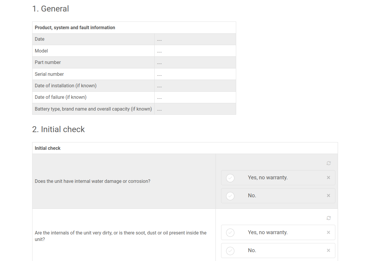
Refer to the Pre-RMA form on the Victron Website, Pre-RMA Bench Test Instructions
Section 2, page 7.
Carry out these checks with no load on the inverter, unless required by the test.
I don’t see page numbers
I ran the bench test but the unit is not working. Comes up with an inverter power overload (Nothing is connected) so don’t know how it is getting overloaded
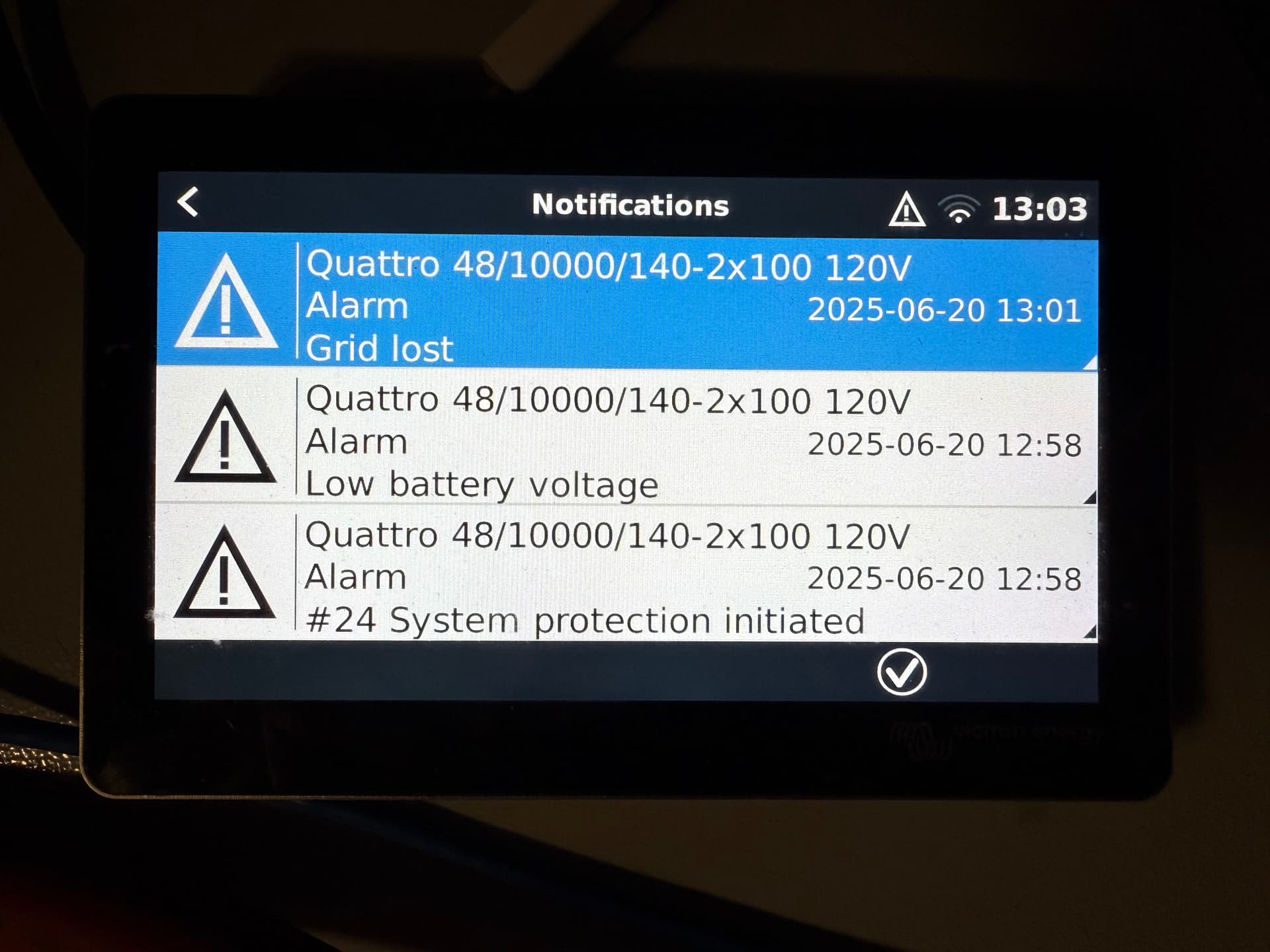
System reported an error 24 as well. As per docs:
Error 24 - Switch-over system protection initiated
This error indicates that one or more units report feeding back a significant current through its back-feed relay, while those relay are supposed to be open, and -obviously- no current can flow through an open circuit.
What is the back-feed relay? It is the relay that closes when connecting to the grid or generator. And which opens when there is no power available, ie when the system is in island- or invert-mode.
Error 24 is raised when a Multi or Quattro detects current flowing through the back-feed relay during a period when the relay should be open. This can mean one of three things:
The relay did not open.
The related current measurement circuit is faulty.
A multiplus II is used with an external current sensor connected, but the option ‘External current sensor connected’ is not checked in ve.configure.
Error 24 is a very rare error. Possible causes in order of probability:
(only on MP II models when using external sensor) the option ‘External current sensor connected’ is not checked in ve.configure.
There is too much AC load connected at the moment the relay needs to switch off. This large current will prevent the relay contacts from opening.
Solution: remove excessive load. See transfer switch capacity in the datasheet for the maximum rating.The AC input voltage slowly drops before it is being rejected by the Multis. Typically happens in installations with a generator. Especially when combined with AC loads that increase their current draw when the AC voltage drops: by the time that the inverter/charger initiates the disconnect, the current through the relays has increased well beyond the ratings, and is too high to open them.
Solution: Make the Multis or Quattros disconnect earlier: increase lower limit of AC input voltage in VEConfigure3. For example to 210 VAC. The factory setting is 180 VAC.The back-feed relay has a hardware failure
Solution: Replace faulty unit.The related current measurement circuit is faulty.
Solution: Replace faulty unit.Diagnosing a parallel, multi or split-phase system?
Error 24 will always appear on all units at the same time. There is unfortunately no indication, not on LEDs, nor on a GX device, VRM, or any other manner, to see which of the devices caused the error. Below procedures outlines how to manually determine which unit has a faulty relay.
Do make sure to first, always double check option 1 and 2 in above list. Those are the common causes. In case that doesn’t lead to a solution, follow this procedure to find out if its a relay issue, and then which unit.
Execute this procedure right after the error occurred; do not first reset the system.
Step 1
Start with making a video of all units and their LED code. Do not first reset the system; and do not reset it after making the video either.
Step 2
Completely disconnect all AC wiring, both in- and out, on all units. Make pictures of the terminals; to make sure when discussing this with an engineer; there is no misunderstanding on what has been meant by this instruction.
Step 3 Now, with an ohm-meter, measure the resistance between the neutral terminals on AC-input and the AC-output, A working unit will show no connection between these terminals. And also measure the resistance between the Line terminals of AC-input and AC-output.
A faulty unit will measure zero or close to zero resistance.
Good units will measure discontinuity between the Line in and out terminals. And measure a few hundred ohms between the neutral In and Out AC terminals.
Recovery: system remains off until restarted.
My system only has one Quattro.
Did the resistance test between neutral terminals and between line terminals. The AC in-1 line terminal to AC out-1 line terminal is showing continuity and is showing 0.00 resistance. All other lines have no continuity between terminals.
Looks like your relay got welded - usually due to switching with high current, something that is not supposed to happen. You will have to RMA the unit for repair.
That makes since. That’s why it’s making a load buzzing noise. It’s the feedback relay trying to open.
Thank you for all the help. I’ll try to post an update when repaired.