Need help refining this design, I am aware I am missing ground connections but is there anything that needs tweaked or changed? Planned on using these panels:
If I am missing any breakers, fuses, components, or have some way to save money let me know. Are both isolation switches necessary?
I live in the U.S. and have a 120/240 split phase connection. I was planning on not using a cerbo gx and instead making my own with a raspberry pi or and an old laptop screen.
One last question, the batteries seem to be about 6-7 hundred USD each, is there any way to reduce this cost via DIY? Ordering cells from china and making one yourself dosen’t seem to be cheaper than these batteries. Please let me know.
1.) 310W panels are very outdated. I bought 450W pannels for 50€ a piece here in europe.
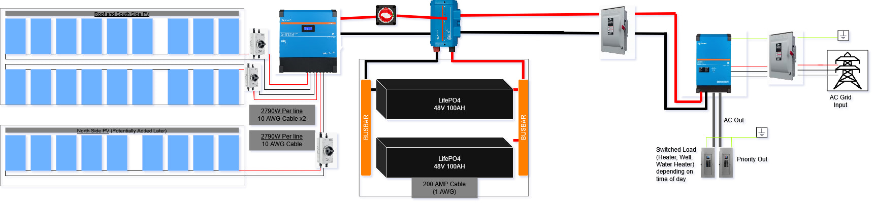
2.) I used fused breakers for the PV strings.
3.) Put a battery isolation switch on the batteries.
4.) A standard linx distributor doesn’t have a Shunt built in. A Smartshunt is mandatory for working with LifePO4 batteries.
5.) I use galvanic isolated cheap usb serial to TTL converters from china for my VE-direct connections to the raspberry pi’s.
6.) Busbars are overkill for 2 100Ah batteries. Just use cabling to put them in parrallel but make sure both cable string have an equal amount of lenght. If you are planning to expand your batteries vastly in the future the busbar does make sense.
7.) It is hard to beat the Pylontech Batteries with built in BMS, they have can bus that replace the need for a Smartshunt.
8.) Your battery capacity is on the low side compared to the solar charger you are unleashing. Be aware that built in BMS current limits are a thing. Also recommended allowed charging current for maximizing you batteries lifspan will limit your charging. Therefore you will probably need to activate DVCC to limit charging.
Given that you mentioned you’re in the US and grid-connected: Are you planning on having this system inspected?
That will bring a whole host of limitations to your design, depending on which version of the NEC your area is on. Assuming NEC 2020+…
UL9540 system compliance. This means you’ll need a “UL1741” listed inverter/charter (Victron has a select few 120V models that are UL listed, so you’ll need 2 of those to generate split-phase 120v/240v). You’ll also need a “UL9540 DC ESS” battery bank (there are only a couple of those out there, such as the Discover Slimline or Helios).
Given your reference to rooftop PV, I don’t think you’ll be able to use the Victron MPPTs in any easy manner (e.g., need arc fault detection, module level shut down, etc.).
Regardless of whether you’re having this system inspected, your utility probably won’t let you use any of the grid-interactive features (i.e., ESS) given the lack of UL 1741 “SB” / IEEE 1541 certs on the Victron inverter/charger.
Exposed wiring is tough in US building codes, so you’ll probably need to think about how to appropriately enclose the AC/DC wiring appropriately to/from the MPPT / DC system / inverter. I believe in an off-grid scenario, inspectors are more understanding.
Need external emergency shutdown trigger for the whole system, for firefighters.
But more so on your diagram:
I’d recommend a bypass transfer switch to supply your AC panels directly from the grid, if you want to temporarily take the inverter out of service.
The two grounds should be connected, and then you have to think about the grounding of the PV array and battery too.
Need overload protection on everything.
Your diagram only shows 1 inverter/charger but you’ll need 2x 120v models (or a 240v model + 2x autotransformers, for the two panels).
I would highly reaching out to a Victron dealer for your design. It’s a big project to do well and safely. My advice above is only meant to help convey the challenges / nuances.