MultiPlus-II shutdown on Low battery with fully charged Seplos LiFePO₄

Hello. I am experiencing an issue with my Victron MultiPlus-II combined with a Seplos LiFePO₄ battery. I am attaching two logs and would appreciate guidance.

System configuration
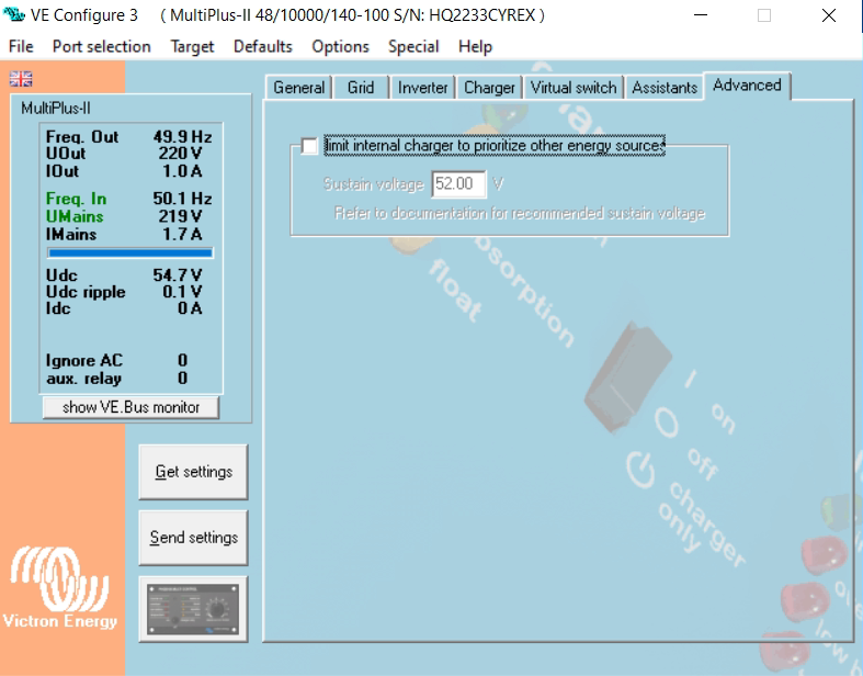
Inverter: Victron MultiPlus-II (48 V)
GX device: Cerbo GX / Venus OS
Battery: LiFePO₄ 16S 280Ah with Seplos BMS (DevBMS/JBD type)

Shown in GX as: Battery Monitor [512]
DVCC: tested ON and OFF

Problem

After a full charge (~55.2–56.0 V), the inverter sometimes shuts down with Low battery / Low DC voltage when the AC input is lost, even though:
the battery is at 100%
BMS voltage does not fall below ~53.3–53.7 V
BMS shows no undervoltage alarm
After manually restarting, the MultiPlus-II works normally.

What has been tested

Recent VRM logs (stable operation):
BMS voltage (Battery Monitor [512].2): ~53.75 V
VE.Bus DC voltage (VE.Bus System [276].9): ~53.86 V
difference only 0.07–0.15 V
Low-voltage thresholds in BMS adjusted
Critical observation from previous log
In a previous AC loss test (log attached), during the transition to inverter mode:

VE.Bus System momentarily reported ~23.46 V at exactly the same moment, the BMS (Battery Monitor [512]) reported ~53.34 V

So the inverter internally “sees” a DC collapse of ~30 V which is not present on the battery side. Immediately after this drop, the inverter shuts down with Low battery.

Additional symptoms

With DVCC disabled, the issue sometimes still occurs

Logs attached

Recent log — shows perfectly stable operation with 53.7–53.9 V battery and minimal BMS/VE.Bus difference.

Older log — includes the moment where VE.Bus drops to 23.46 V while the battery stays at ~53.34 V.

Questions

What could cause VE.Bus to momentarily see 23.46 V, while the battery remains at 53+ V?

Could this be related to:

internal DC sensing in MultiPlus-II
BMS data timing vs actual voltage
Do ESS/DVCC use different internal low-voltage thresholds not shown in VRM?
Recommended low-voltage settings for 16S LiFePO₄?

Thank you very much. More logs can be provided if needed.

Home_20251202-1630_to_20251202-1639.csv (27.2 КБ) - 10 line - 23.46V

Home_20251202-2221_to_20251202-2321.csv (49.8 КБ) - 60 line - DVCC was disabled and Low battery L1 showed alarm

What’s the power of Multis? Maybe 1 set of seplos is not sufficient. I have 2 sets, when 1 broke due to bms problems, I had low voltage issues with other one.
Maybe seplos is too slow for peak demands and is showing wrong values? Now with 2 sets all is working ok.

Thanks for your reply!

It’s a single Multiplus-ii 48/10000 (one unit, not paralleled) and one Seplos pack: 16S LiFePO₄ 280 Ah. So on paper this one battery should easily handle the actual loads I had during the tests.

What makes me think it’s not (only) a “battery too small / peak current” issue is what I see in the VRM logs at the moment of the shutdown:

  • BMS (Battery Monitor [512].2) shows about 53.34 V and 0 A battery current

  • VE.Bus System [276].9 at the same second suddenly drops to 23.46 V

  • Output power (VE.Bus System [276].8) is only ~400 W → ~268 W, so nowhere near the limit of the inverter or the battery

So the pack voltage from the Seplos side is rock-steady around 53 V, there is no high surge current recorded by the BMS, and the load is quite modest – but the MultiPlus briefly “sees” something like 23 V DC and then shuts down with Low battery.

I totally agree that having 2 packs in parallel reduces internal resistance and makes life easier for both BMS and inverter (I’m actually considering adding a second pack later), but in this particular case the strange thing is that only the VE.Bus measurement collapses, while the Seplos voltage stays flat. That’s why I’m trying to understand whether this could be:

  • some glitch in the DC sensing inside the MultiPlus-II,

  • an issue somewhere on the DC path between battery and inverter (fuse, switch, busbar),

  • or something related to timing / interpretation of the values in DVCC / ESS.

So I don’t exclude that one Seplos set might be on the edge for bigger peaks, but the logs for this event don’t show any real peak current or cell sag on the BMS side – only the VE.Bus voltage drop.

Some bms read their voltage before the disconnect circuit.

So potentially what could be happening is the output of the battery is disconnecting leaving the inverter with no power but the battery itself reads the full voltage.

It can happen on some batteries with smaller loads like it is a parasite draw protection that is a it aggressive..I have no experience with seplos, so cannot say for sure there. Just something seen elsewhere.

In the ess cut off voltages what do you have set? Not ruling out programming either here yet.

1 Like

I had the exact same issue with one 5000kVA MPII + one Dyness 5.12KW pack. Despite any settings, loosing AC got battery DC low voltage and shutdown.

Adding a second Dyness battery pack solved all problems and system is working perfectly.

Datasheets numbers are nice and math should work but it looks like Victron inverters are demanding, and very short burst of high current is kneeing the BMS.

1 Like

Yep, it’s quite stupid but it’s working like that.

But other brands doesn’t have such problems. I’m supervising some installations with ZYC battery (5hWh bricks stacked together for 10 or 15kWh) and there were never any problem. Although I haven’t tested any system with only 1 battery unit of ZYC for longer time, only during commissioning.

For the Seplos - it’s good to take a look at Helmut’s settings and adapt some of them for your system (see topic below):

Most BMSs tend to refresh every 3-5 seconds (or even more rarely), so it would be a hit or miss timing issue to get the correct values (i.e. a momentary voltage sag) recorded over to a victron system log.

That said, examining the logs brings up a number of “high DC ripple” events on your logs, a minute or so after your “low voltage” shut down. This could indicate a case of the BMS being unable to support the DC bus properly. What’s the maximum discharge current supported by the BMS?

Victron’s inverters use the DC bus’ “capacitance” extensively while supporting high transient currents. That’s why you should make sure your battery-to-inverter cable gauge is at least what is described in the manual.

1 Like

Here’s a relative conversation with an AI agent:

https://grok.com/share/bGVnYWN5LWNvcHk_9b68a475-9302-43bf-b9a6-90a3a2ed8f74

Consider the quotes as well.

For sure you got the actual meaning, access to large energy quantity over a very short period of time, a real challenge for most of BMS-es and the reason of much stable systems when more than one BMS is in parralel.

Another approach is a much bigger difference between BMS datasheet capacity and inverter.

1 Like

@Lisciasty You are funny. If those “formulas copied from somewhere” were wrong, Victron wouldn’t require minimum cable gauges for their connections, a pair of 1.5mm² would suffice in any configuration.

Ok I’ll lose some more time, anyway.

  1. Formulas may be ok, but whole “conclusion” says “it may affect”. Tell me where to find percentage of this affection? Is it 40%? Or maybe 0,1%?

  2. Where in Multiplus you have high frequency ripples, when this system is old-fashioned low frequency converter?

    Stupid AI won’t help you if you don’t understand basics. Plus AI answer without specific values is only a waste of energy and time.

Thanks for the explanation, and I fully agree with the idea behind those quotes - accessing a large amount of energy in a very short time is exactly where things get tricky for BMS and why parallel packs often behave “smoother”.

Just to add some more concrete data from my side:

  • I measured the inverter start current with a clamp meter and I saw a peak of about 120 A for a very short moment when the MultiPlus switches to inverter mode.
  • The Seplos BMS / pack is rated for 200 A continuous discharge, with protection limits around 210 A and a transient limit of about 300 A (according to the BMS parameters).
  • So on paper, a ~120 A spike should still be well inside what this single pack is designed to handle.

Of course I understand that:

  • the clamp meter may not catch the absolute peak (so it might be a bit higher in reality),
  • internal resistance of the cells + BMS + cabling will still cause a voltage dip,
  • and having two packs in parallel gives a much bigger dynamic buffer and makes everything less sensitive to these spikes. I completely agree that your setup with 2 packs is more stable by design.

What still looks strange in my case is this combination:

  • BMS voltage stays around 53.3-53.7 V, no sign of serious sag from the battery side,
  • BMS current at the moment of the issue is logged as 0 A (so not even a visible discharge spike in the VRM log),
  • but **VE.Bus DC voltage briefly collapses to low level and triggers Low battery shutdown.

But right now I’m trying to understand whether what I’m seeing is:

  • simply the limit of having one pack close to its dynamic limits,
  • or something like an issue in the DC path / sensing / wiring, since the BMS doesn’t see that low level event at all while the inverter does.

In other words: I do agree with your principle about peak power vs BMS capability, I’m just a bit puzzled that in my logs the BMS looks perfectly happy at ~53 V when the MultiPlus decides it has seen 23-40 V and shuts down :blush:

And main question, when I press power on manually all going fine, but invertor can have more loading because need to start refregerator motor for example and there can be more one time loading then normal mode.

Good writing and definitely interesting topic. For sure will help DIYers in future projects.

Regarding possible issues with wiring, contact points etc. a IR camera or simply measuring voltage drop under significat load will show weak spots.

Another interesting fact, two locations, identical MP-II GX, one with 2 x 5.12kW Dyness and other with 1 x 14.33kW Dyness.

Logged DC ripple is 50% higher in single battery location, under similar loads.

I am tempted to take some time and use an oscilloscope with high sampling data logging, for current and voltage, in the hope of catching the troublesome behavior.

1 Like

i had the same problem here - please try to switch off battery observation in MP2 - has to be done with VEConfig

MP2 observes the batterym regardless of the settings in Venus

In any case, since you still haven’t mentioned it, please make sure your cabling is according to specs, or bigger.

Hello, yes, this option was already disabled, for a better understanding of the settings, I am adding all pages

Hello. I took the thickest cable I could find.

3rd picture - DC Input Low Shutdowb - could you reduce that?

Maybe try to use dbus-serialbattery to use the BMS values instead of the internal measurement?