MultiPlus II not detecting or charging from 30A, 15A/20A shore, or generator

First post, I am new to Victron and these systems. I have a 50A RV with a Victron MultiPlus II inverter/charger and Cerbo GX, professionally installed by others January 2025 along with 1600 W of solar and (2) Victron MPPT. The coach also has a factory Onan Marquis Platinum 6500 LP generator (single-phase, 2 x 30A onboard breakers) that’s worked flawlessly for 20 years.

On 50A shore power, everything works perfectly — both L1 and L2 show on the Cerbo and charging works as expected. But I’m seeing issues on any single-phase source:

•	30A shore: Cerbo display shows “Shore Disconnected” (at least for one leg), sometimes charging occurs but I also get VE.Bus System [276] Overload L1: Warning in VRM alarms.
•	Generator: No charging at all, Victron doesn’t seem to register AC input.
•	15A/20A outlet: Using standard adapters from my 50A plug down to a household outlet, the Victron won’t charge at all.Installer suggests this is a "bonding problem" somewhere in my RV's wiring.
•	Ford Pro Power 120V outlet: Plugging in immediately trips the truck’s outlet into error mode. I’ve heard this may be related to neutral–ground bonding. I will pursue this challenge separately but I include here as background.

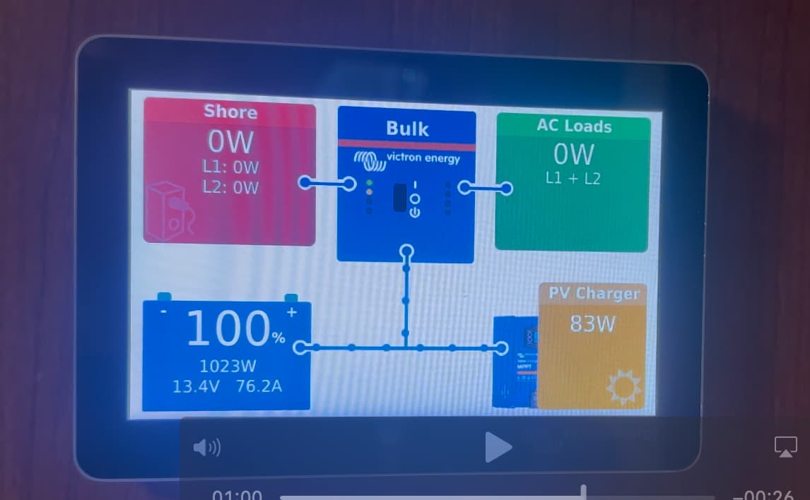
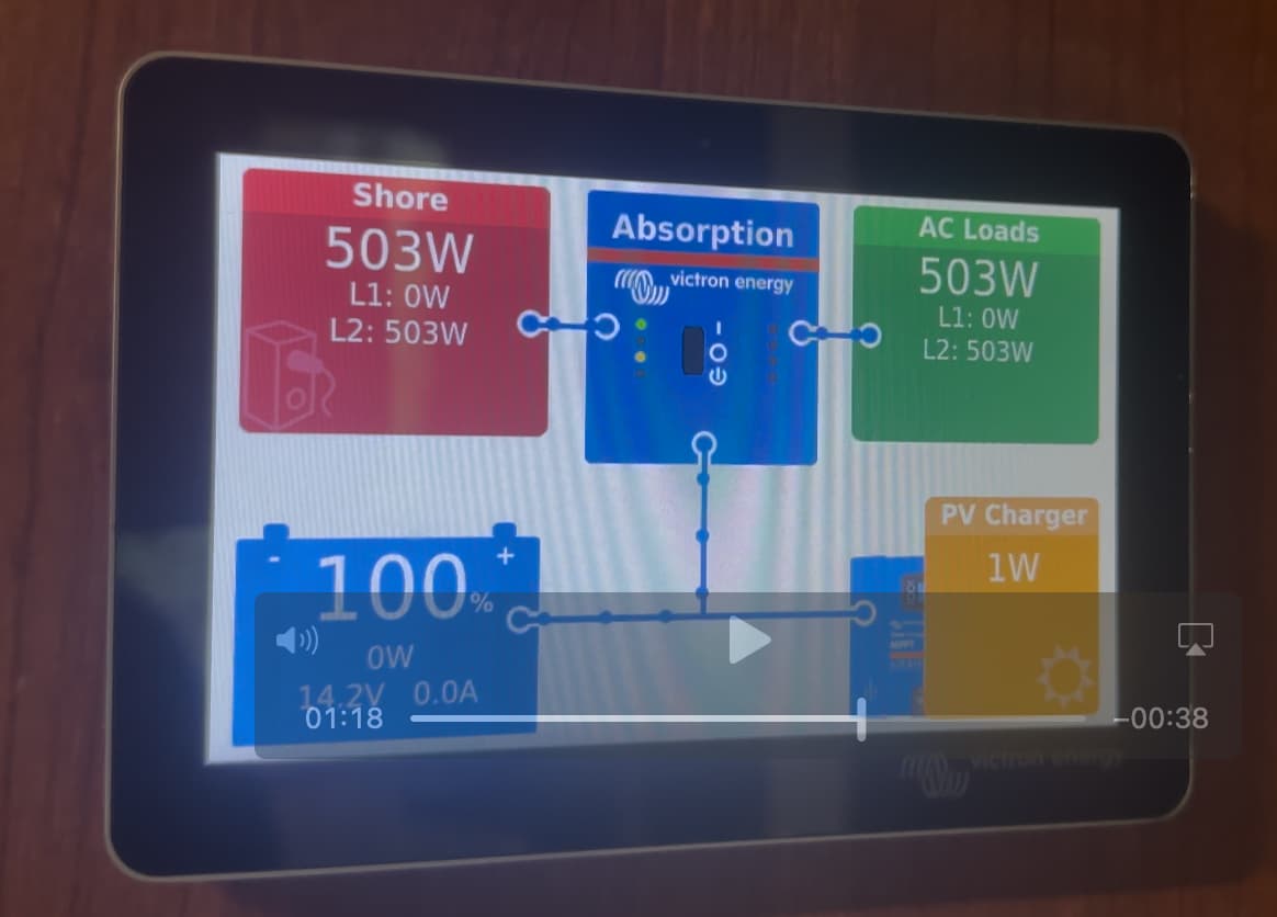
When I was using 30A shore power and experiencing the Shore Disconnected message, my installer remotely determined the system was “working” (=charging) despite the erroneous disconnected indication. Later, a separate source suggested that the overload warning might indicate on single-phase sources, only L1 is powered and all loads are stacked there, and with L2 unused, that the Victron is wired/configured for 50A split-phase without an L1–L2 tie when on single-phase inputs (30A shore, generator, small outlets).

Questions for the group:

1	How should the Victron’s AC inputs be wired so that single-phase sources feed both legs?
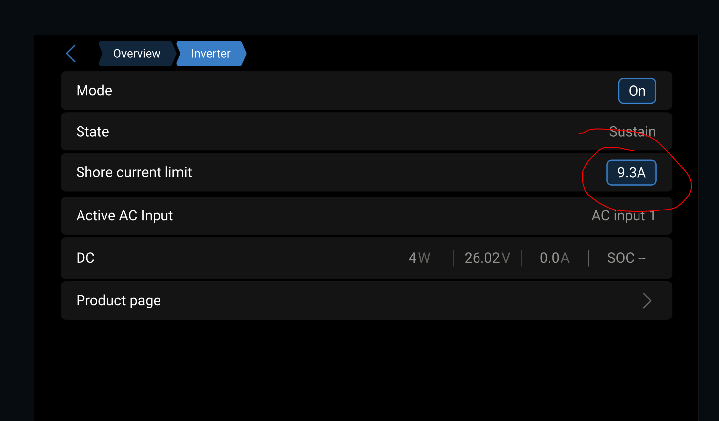
2	What’s the correct Victron configuration for switching between split-phase (50A shore) and single-phase (30A shore, generator, small outlets)?
3	If all components are installed and configured correctly, are there any known "glitches" that would cause the system to report incomplete or erroneous information? Am I unreasonable to expect this system to operate and display flawlessly and automatically as I move between 50A, 30A, 20A shore power and inbuilt generator?
4	Is safely running the Victron from my Ford Pro Power 120V outlet without tripping it related at all or should I pursue that separately?

Equipment:

  • Inverter/Charger: Victron MultiPlus II 12/3000/120-50 (FW 2780552)

  • Charge Controllers: 2 × Victron SmartSolar MPPT 150/60 (FW 3.16)

  • Monitoring: Cerbo GX with Touch 50 (FW v3.60)

  • Batteries: 10 × 105 Ah Lion Safari UT 1300 (LiFePO4)

  • Solar: 1,600 W roof array (8 × 200 W Renogy panels)

  • Generator: Onan Marquis Platinum 6500LP, auto-start via Onan EC-30

  • Shore Power: 50 A

  • Other relevant gear: Battery Heating System, Hughes Autoformer, Surge Guard RV Power Monitor #34750

Thanks for any guidance — I’d like the system to work seamlessly from all AC sources without overload warnings or missing charging.

Is this a 2x120 MP2? Have you tried removing/bypassing the hughes autoformer and /or the Surge Guard? Are you attempting to carry large loads such as microwave or air con when getting the overload warnings? If so, you might try lowering the boost factor.

It is a single unit, Product ID 2780, MultiPlus-II 12/3000/120-50 120/240V. Does that answer your question? (sorry)

Yes, the first time I connected to 30A service I experienced the Shore Disconnected issue. I immediately removed the Hughes Autoformer and the Surge Guard. No change.

I did not personally set the boost factor and so I’m not sure how to check that setting. But I will make a note to review this. Thank you very much.

Is that a 2x120V model? The MP 2x120 models have L1 & L2, but the pictures in the MultiPlus II 12/3000/120-50 manual only has a single L1 input. The charger is on L1 only.

I have a MP 2x120V in my coach. My 30A dogbone ties L1 & L2 together into the 50A shore cable.

Based on Product ID 2780 — I have the MultiPlus-II 2×120 V model. And I have seen both the L1 and L2 readings active at various times.

I’m doing some testing at home today, with 50A shore power installed. I turned on two roof air conditioners and an electric fireplace. During this test the AC Load reading was around 500 watts, which is clearly wrong. During this test with two A/Cs and the fireplace going simultaneously, I received a VE.Bus System [276], Overload L1: Warning. Any thoughts? It seems some aspect of this installation is mis-wired or misconfigured?

Okay, that sounds about right. I’ve never seen them referenced by model numbers, not even sure where to find that info.

I haven’t had mine on 240V service, but the Wattage I’ve seen on the Cerbo has been pretty accurate. You really shouldn’t see an inverter overload on shore power, unless you have Shore Current Limit set too low for the load and the inverter is assisting? Now that I think about it, that would limit your shore Wattage to a small value AND give you an inverter overload because 2 AC are far too much for your inverter with only 500W from shore (I tried it recently).

What do you have this value set to?

Thanks, Paul. Because I wasn’t sure what I have I looked up my model # in VRM>Devices. Shore limit in my settings is 50A for true 50A service. On 30A or generator, I drop the AC input limit manually, but I’m still seeing one leg show zero volts/amps in the Cerbo GX, which is why I think the L1–L2 tie for single-phase sources may be missing.

Another test is to unplug shore and try the AC & fireplace to see if each will run from the inverter (one at a time). IF they don’t, they might be wire to AC out2, which is only pass through when on shore. The inverter is on AC out 1 only, but is switched to L1 & L2.

My coach originally had a 30A pass through inverter. 50A (L1 & L2) shore wired into the main breaker panel, with a 30A (L1) breaker feed out to the (old) inverter, returning to a 2nd breaker panel that feed a few circuits (microwave, TV, a few plugs). The remainder, water heater, both AC’s absorb refer plug, all on the main box only worked on shore.

My L1-L2 tie for 30A is in the dog-bone adapter. Your generator is single phase, but might have two 120V outputs. I’m pretty sure the generator in my gasser had that arraingment, and I know for sure my diesel genset does.

I unplugged shore power. I turned on the fireplace and it works under inverter and the AC Load reading increased up by 1100 watts, which is expected. I turned off the fireplace and turned on the air conditioner. The A/C turned on by inverter and the AC Load reading settled at about 1700 watts. So, yes, these loads are inverted. From my installer’s orientation it is my understanding that my entire AC panel is inverted except for a new CheapHeat system that is wired thru a separate sub panel. CheapHeat is only energized when on shore power.

Here is something curious to me. While inverting, we saw the AC Load display reflect the fireplace or air conditioning being turned on and off. But when connected to shore power neither registers on the Victron AC Load total.

Example: right now I have 50A shore power connected. Line 1 Amps and Volts are reading 0. Line 2 Amps are 4.0 and 522. When I turn on the 1100 watt fireplace, the fireplace turns on, but the Line 1 still reads zero and Line 2 does not reflect any change. Same with air conditioning.

Since I’m new to the forum today, I’m not sure if I am permitted to upload any screenshots.

That’s odd indeed, but it confirms all of your loads are on AC out1. Just checked, mine will show pass through Watts. I’m only on 120V, but it should be the same for 240V.

It could be some firmware oddity in the Cerbo, but it seems unlikely.

It almost feels like your inverter is bypassed on shore. Is your MP AC input wired to the input side of your transfer switch? I think you mentioned it didn’t charge from the generator?

You should be able to post screen shots. Cut & paste one in.

Thanks again for your feedback, I really appreciate it. Unfortunately since I didn’t install this system or watch the installation process, I don’t know how the MP is wired to the transfer switch.

Last month on the way home from a trip, the RV park we were stayed lost all utility power on a 95° day. We thought we could start our 6500 watt propane generator and run one or two air conditioners just like we have done in the past 20 years. We got no power from the generator, though the inverter could run an air conditioner. Later I found one of the Onan’s two 30A breakers was tripped. I turned it back on but we still receive no charging and no shore power from the generator.

My goal today was to get a third party perspective on what’s normal behavior. My installer will review all this next month under warranty. I don’t know if my transfer switch is operating correctly- what I do know is that all these problems only started since recent Victron installation.

Zooming out: am I correct that all I have to do is manually set the AC Current Limit according to the shore or generator provided- and the Victron system should seamlessly and automatically invert and charge on 50A, 30A, or 20A shore or generator power and correct incoming Shore Power and AC Load information should be displayed?

The solar charging and inverting from the solar-charged battery bank seems to work perfectly, by the way.

Sure, set the shore current limit to the max you want to draw, and it should do it’d thing on grid or genset. I have mine set to minimum 9ish Amps in the barn here during the renovations. I use a heat gun, shop vac, AC, anything inside the coach and the MP will make it work and display what it’s doing on the Cerbo display.

I still think the transfer switch wiring is involved, it will be interesting to see what final the solution is.

On the inverter (behind the wiring access cover) there is a jack for an external current sensor that looks like a headphone jack. Grab a set of headphones or something else of similar size plug and plug it into the jack and remove it a few times and see if that corrects the problem.

After a second read, you might have a transfer switch problem. With the rv connected to 50 amp shore power, check the shore input and breaker panel output of the transfer switch. You should see 120v from L1 to N, and L2 to N, and 240 between L1 and L2. If that checks out, then check the ac input at the inverter.

Thanks, Derrick. The inverter might be a little difficult for me personally to access, but I will try to check the external current sensor and report back. Thanks also for relaying a concern about the transfer switch. AFAIK this is the same factory ATS from delivery in 2004. When my RV goes back to my Victron installer next month, I’d like to send a new ATS along in case a replacement is warranted. Is there a preferred ATS in regards to interacting with Victron systems? I was considering this Go Power ATS, which seems to physically fit in the same space as the factory original.

Lastly: my installer has suggested that the reason my RV is completely unable to charge from a 20A outlet (the Victron just won’t accept the power) is because of a neutral bonding disorder which causes the MultiPlus to shut down- and that this bonding problem is probably buried somewhere inside the wiring of my twenty year old RV. Does this sound reasonable? Installer has suggested he would need to manually hunt through my RV wiring to find the source of the bonding and alleviate it before the MP will charge from a household outlet. Of note: during one trip I was able to charge from a smaller portable generator with a 30A outlet, I plugged the RV’s 50A power cable into a 30A adapter and plugged that into the portable generator, and the MultiPlus used that power to charge the batteries.

Instead of the bonding issue being the cause, could the inability to charge from 20A be related to an installation wiring choice and/or configuration error, somehow related to single phase, L1 and L2 confusion, and L1 / L2 tie ins discussed above?

Bonding the AC ground to chassis ground is usually a large bare wire from the breaker panel to the chassis, both of my coaches had that wire. I doubt that’s the issue.

The MP only charges from the L1 input. The 20A to 50A adapter should tie L1 & L2 together. If that tie is missing, OR the installer has L1 & L2 swapped, it won’t charge.

Some measurements need to be taken with a vom as previously described. Until that is done and the results examined, anything else at this point is pure speculation and a waste of time. A vom is your best friend when trying to diagnose electrical issues.

Hi, all. Thanks for your patience, I needed a little extra time to gather some data.

In a series of tests, I provided power to the RV from four different sources (50A, 30A, 20A shore power, and Onan Marquis 6500LP generator). In each case I manually changed the Multiplus current limit to 50A, 30A, 18A, and 30A, respectively. I recorded these findings in long videos, later pausing playback to transcribe all values and they appear below. I had to scroll the small display many many times to capture all the data. I apologize, I imagine seeing photos of the actual display would be more familiar to you, but here comes the findings.

Shore Power from 50A Utility Power:
Victron Switch: On
Current Limit: 50A
L1: 124V
L2: 124V
AC-In Line 1: 127V, 0.0A, 0W, 60.3Hz
AC-In Line 2: 125V, 4.0A, 494W, 60.3Hz
AC-In Total power: 494W
Cerbo Display: Red Box Active with L1: 0W L2: 503W
Observation: none
Further: Turned Victron Inverter Off, All AC Loads Work Normally including A/C

30A Power from EcoFlow Delta Pro
Current Limit: 30A
Victron Switch: On
Active AC Input AC IN1
AC-In L1: 122V, 0.0A, 0W, 60.3Hz
AC-In L2: 120V, 0.0A, 0W, 60.3Hz
AC-Out L1: 122V, -13.6A, -1447W, 60.1Hz
AC-Out L2: 122V, --, 0W, 60.1Hz
AC-Out Total power: -1445W
Cerbo Display: Red Box Inactive Shore 0W, L1: 0W, L2: 0W
Observation: Loud Hum from Victron stack; Cerbo Display marching ants indicate charging is 1034W

20A Power from EcoFlow Delta Pro
Current Limit: 18A
Victron Switch: On
AC-in L1: 122V, 0.0A, 0W, 60.3Hz
Ac-in L2: 121V, 0.0A, 0W, 60.3Hz
AC-OutL1: 121V, -13.6A, -1437W, 60.1Hz
AC-Out L2: 121V, --, 0W, 60.1Hz
AC-Out Total power: -1437W
Cerbo Display: Red Box Inactive 0W
Observations: hum coming from Victron stack, Cerbo Display marching ants indicate charging is 1024W

30A Power from Onan Marquis 6500LP
Current LImit: 30A
Victron Switch: On
AC-In L1: 120V, 0.0A, 0W, 60.3Hz
AC-In L2: 119V, 0.0A, 0W, 60.7Hz
AC Out Line 1: 119V, -13.2A, -1385W, 59.9Hz
AC Out Line 2: 120V, - A, 0W, 59.9Hz

Cerbo Display: Red Shore Box Inactive 0W
Observations: Red Box Shore Inactive 0W, Cerbo
Display marching ants indicate charging from generator is 1007W
Further: Turned Victron Inverting off, AC loads electric fireplace and espresso machine work normally. But turn on one Air Conditioner and A/C starts but 15 seconds later A/C turns off, all AC loads are off while generator continues to run, Victron indicates Fault. No AC power present at any devices until power cycle Victron.

Preliminary thoughts on what this means.

Sounds like PICNIC could be at play. That’s an acronym for Problem in Chair, Not in Computer. In other words, user error.

Here’s how the story unfolded:

I am new to Victron. At home on 50A I was accustomed to the Cerbo Display’s red Shore box being active, showing incoming power and watts. On my first trip and first time connecting to 30A shore power, I was dismayed to find this red box reading 0 watts. I incorrectly concluded the system was not charging, but it was.

I have since received an opinion that the red box showing 0 watts is normal behavior on 30A or 20A. Not sure.

On that same trip I traveled to the next RV park which again had 50A service and the red box was active again.

On the way home I stopped at the last RV park, which happened to be actively experiencing a utility power outage. I turned on the Onan generator for the first time and suddenly nothing in the coach had power and I was unable to run either air conditioner by the generator. At home I found the Onan genset circuit breaker 1 flipped off.

You’ll notice in my test above that during the Onan test, everything was working until I turned on the air conditioner and fifteen seconds later all the AC loads turned off and the Victron displayed showed FAULT. This is probably what happened earlier in the summer at the RV park with no utility power.

My goal is to have this large generator’s 6000 watts maximally available, allowing the MultiPlus to charge at full speed while handing over additional power to run microwave, espresso, etc., as needed.

I don’t see evidence of hardware at fault, from Victron to Onan to ATS. Possibly the way the Onan is wired to Victron or perhaps configuration changes are needed.

I appreciate all your help and attention, along with any guidance you might share. Thanks again.

Attachments: in the first image, 30A shore power, you see the red box Shore indicating 0W even as marching ants indicate charging is occurring. In the second image, 50A shore power, you see the red box Shore with 503W on L2.

You really need to get a schematic.

You stated the when you switch off (the 3-way switch to “0”?) the MP II, your loads continue normally. That means the MP II is automatically bypassed.

And when you use the EcoFlow, it appears you are charging the EcoFlow, judging by the '-’ sign.