Just tested at 93% SOC and the total voltage drop is 800 millivolts.
So that makes 500 millivolts over the cells, resulting in 31 millivolts per cell.
I also see that it takes a few seconds to stabilize, first it drops with 600 millivolts and after a few seconds it settles at 800 millivolts drop.
When I go back to charging, the difference is only 500 millivolts between discharging and charging voltage at 16 amps, and after a minute the difference is 700 millivolts between discharging and charging voltage.
No, no, no.
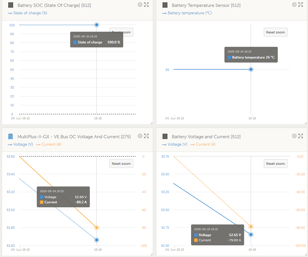
Jeroen, I told you that for a clean measurement it must be make from Idle state of the battery, when the SOC is 100% and the battery voltage 53.4 (3.33-3.35) per cell.
Subsequent measurements are made in the same way. For accurate conclusions, it is necessary to record only the peak of the drop under load.
Yes, you need to wait until the cells are at rest. 3.33-3.35 total 53.4V
Then you apply the load and measure the peak drop.
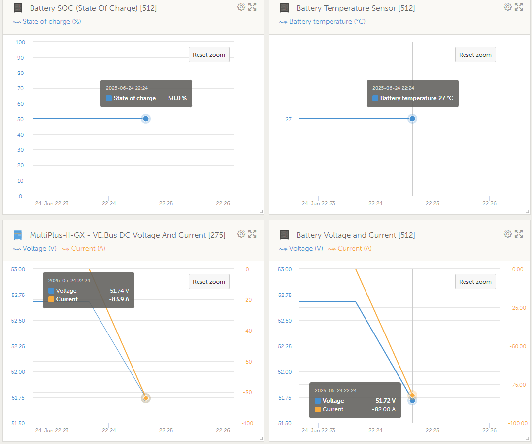
After that, discharge the battery to 50%, stop the discharge, turn on the idle mode, wait few hours to stabilize the voltage.
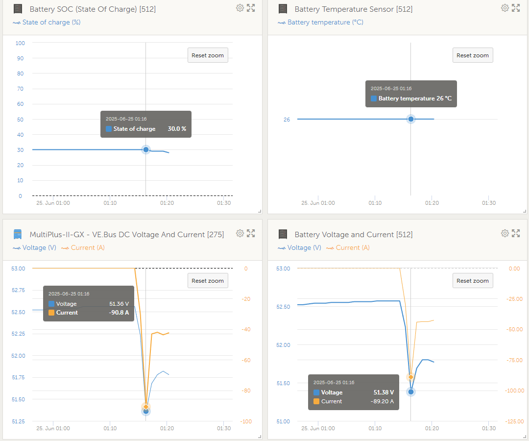
And so on at each charge level, next level 30%.
UPD: Once you have all off the peak voltage drop values, you can make a general assessment and start calculating the values for Dynamic cut-off and adjusting them.
A few hours later, the battery voltage is still 55.12 volt. Should I still wait?
Or would it be better to discharge to approximately 53.4 volt / 99% soc, let the system idle for a while, write down voltage, start discharging, write down voltage again and calculate voltage drop?
I show you how important it is to make accurate measurements to calculate the values correctly. And what are the dependencies on the residual capacity, how does it change in values.
And finally I finished the presentation of the measurements & trend drop voltage in battery, with the different residual capacities.
My data (Not applicable to other installations, just as an example)
SOC 100% - drop 0.70V
SOC 50% - drop 0.95V
SOC 30% - drop 1.20V
Based on the received data, we make a calculation for “Dynamic cut-off” values ESS.
99 or 100 is not important.
The important thing is the resting state of the cells & upper voltage of 3.33-3.35.
By measuring the entire range I immediately identify many problems, if they exist.
Experience
UPD: I was a little alarmed by the values in the start post.
But now I don’t see anything critical.
Now you need to make adjustments to the values for ESS “Dynamic cut-off” & Inverter “DC input low”.
And everything will be fine.
So when I take the worst value, of 1 volt drop at 88 amps, I get the following result:
0,005C = 0,0178V drop
0,25 = 0,8920V drop
0,7C = 2,4977V drop
2C = 7,1363V drop
The idle voltage of a cell at 10% is 3 volts and at 10% it is 2,5 volts. So I’ll take in between 2,75 volts as minimum voltage (+/- 5%) which is 44 volts for the battery so it never depletes to 0%.
Dynamic cut-off 0.7C & 2C = Victron DC input low shut-down
Because you can’t take more than 4-4.3 kW from your battery.
You are limited by the inverter power.