MPPT RS 450/100 connected only to battery.
PV not connected.
Every 30-40 seconds, the battery consumption increases briefly (by about 200 milliseconds) to 10 amps.
Is that how it should be?
Thanks.
Definitively not.
Being an MPPT, the flow of energy must be only from PV array to battery.
Otherwise, I don’t find any other reason…
Or, maybe:
- For 0.2 seconds, from time to time, the device wants to know the state of charge of the battery ??..
But it seems too complicated to do it this way… - It needs to charge-up the high voltage DC bus capacitors, in order for a smooth functioning ??..
- Or a combination of the above - charging the HV capacitors will also verify SOC.
- Or a glitch in the firmware.

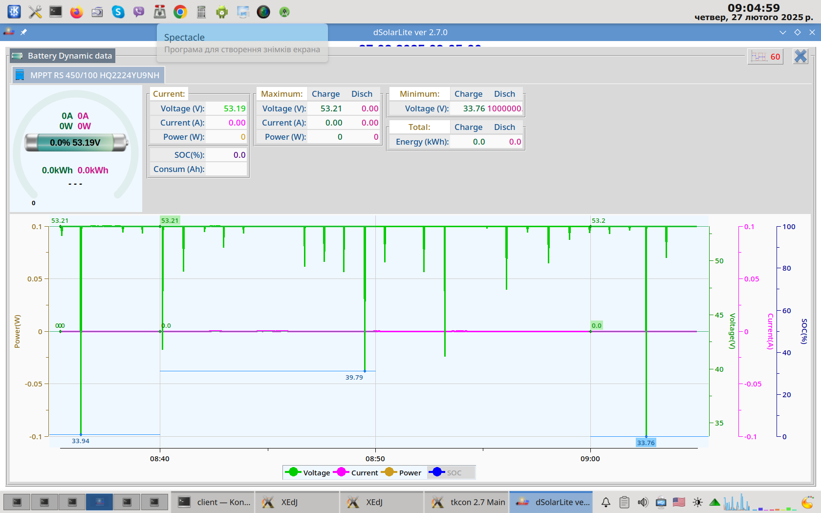
Please, look at this screenshot:
Screenshot: voltage and current graph
Congratulations!
I processed the data from MPPT RS in my monitoring program.
I connected the device to a power supply with current stabilization of 10 Amperes.
You can see the pulse consumption, as a result of which the voltage drops (because the current is limited to ten Amperes). The current on the graphs does not change. Obviously, this is due to the fact that the current sensor is located after the problem section.
That is:
battery → problem section of the circuit → current sensor → the rest of the circuit.
The device after repair.
Are there still problems, or is this normal behavior of the device?
I have a similar issue with a 450/200 except the current spikes are 160Amp for 0.2 seconds around every 104seconds (seems variable with temperature between 98 and 114 seconds). Occurs whenever there are no panels connected or it is night time.
Average power looks to be about 1Watt.
This has to be a fault or it’s the worst designed every by very incompetent engineers.
I reported this to Victron a year ago.
It seems they haven’t fixed anything.
Victron are proving impossible to deal with. It seems only their Engineers are so incompetent that they think 160amp pulses during the idle state is acceptable.
Did you resolve this issue and continue with Victron or go another way.
The problem was not solved.

I’ve seen such situations when the reads/writes of variables that are also processed by the interrupt functions are not atomic.
As the drive logic of a H bridge is usually done inside an interrupt function, God forbid to have at some point both upper and lower FETs from a H bridge configuration in ON state. It will create a short across the battery.
Not saying that this is the case here, but timing of a H bridge, even if it’s done with the help of the PWM peripherals from a microcontroller, is tricky and if you don’t allow enough time for the FET recovery during switching states, you can go into trouble, especially if the FET manufacturing batch is slightly out of specs…
With my 450/200 the pulse is 8.8kW for 0.02 seconds. Certainly could be an H bridge overlap. Weak gate driver or higher capacitance gate or even black market inferior parts substitution.
Whatever the cause is it’s unacceptable and Victron need to get it resolved. As it doesn’t have any error codes I’m told I should so just go away and ignore it.
The MPPT RS range keeps the high voltage bus powered on for various reasons. If you don’t have solar input, then it takes power from the battery through the DC-DC converter.
Those are the pulses you see, it’s normal and expected.
Glad that it’s now clear. 
So it was my number 2 assumption.
Thanks for contributing here. Perhaps you could clear up the question about the magnitude of the current pulse I have on my system. Why does it need to be 160Amps for 0.02 seconds every 114seconds ? to deliver 1.5Watts to the internals that needs to remain powered.
The DC-DC converter is not powered on all the time to reduce waste of energy. It is powered on when the high voltage DC bus needs a '“fill-up”.
That’s why you see this regular pulse.

Thanks for the answers here.
My questions is why does the current pulse need to be 160Amps to supply what is specified as a 0.8Watt (15ma) standby supply.
160Amp pulse seems very excessive to me to be drawing from the battery.
Logs of my 450/200.
Current Spike Fast Log.pdf (274.3 KB)
Current Spike Fast Log Zoom.pdf (253.2 KB)
Please don’t mark this topic as resolved when there are still outstanding questions about the amplitude of the current pulses and if 160amp is normal operation in standby mode.
You probably know this, but it appears because you need to charge the parasitic output capacitance of the FETs.
That alongside with the inductive load spikes.
I am thinking about 3-4 methods to do this, but with the current hardware configuration, don’t know if you can avoid that.
Maybe only with a software trick, but if you use a 2 channel DSO on the low and high side FETs, you will see that now this is not the case.
Through software, maybe a phase shifted PWM soft start could be implemented, in that way that you keep both low side switches on while slowly shifting the phase of the high side switches from 180 deg. out-of-phase - so zero net voltage - to the operating phase angle.
But probably Victron considers it’s not worth it, as the FETs seem to be able to handle the current and the spikes are too narrow.
PS.
The solved mark was not put by Doro (the OP), which also considers this a “terrible situation”, but he can uncheck it, if he considers it necessary.
Thanks for the insight. With 160Amp on wires external to the MPPT, wire and battery I2R losses probably dominate any internal switching losses. So while the MPPT might look good on paper the reality in a system is likely very different. The current amplitude seems to be directly proportional to the period between the top up pulses. I would like to see the pulse period decreased to around 10seconds from my current 98 to 114seconds. This would hopefully bring the current pulse down to 10amps which I would consider far more reasonable the160amp pulses I am measuring. If efficiency is important I would think a small 2W DC/DC converter with correctly sized fets etc would be more efficient than utilising existing large power fets.
In any case I would Victron to state what current pulse is considered normal and within specification. Unfortunately I have a feeling the designers are relying on external impedance to limit the current draw and keep it below damaging levels. AKA Cost Cutting.