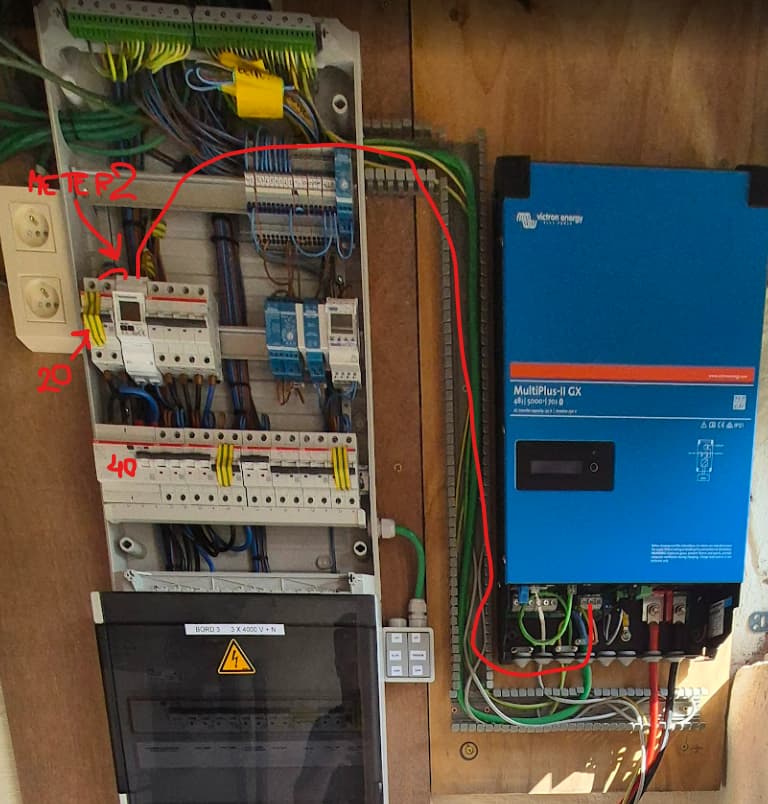
OK well that isn’t a layout you would see in the UK but I am also not seeing anything obviously wrong and different to my expectations doesn’t mean bad in any way.
In fact it looks well put together, from what I can see.
Clearly that is a 3 phase board and it appears that you are only using a single phase and have single phase meters, at least associated with the Victron.
Cable sizes and lengths ‘look’ OK, again so far as I can tell, I am not suggesting I have done any calculations, have an knowledge of your country’s regulations or even this specific systems design details, but they look sensible…
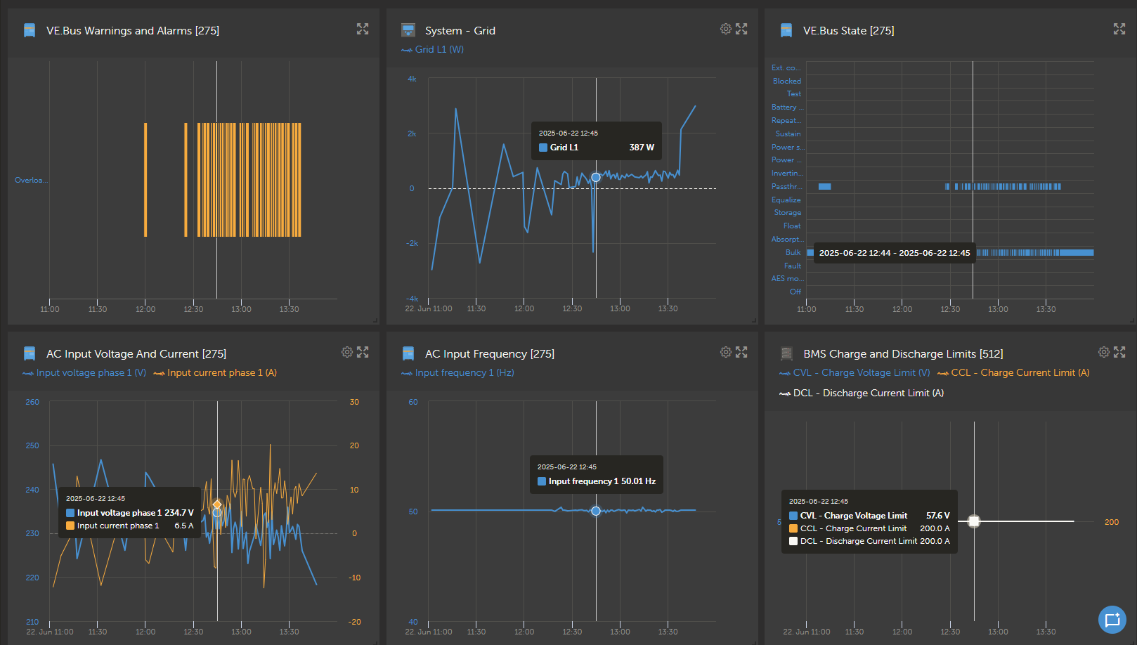
That brings me back to voltage swings…
Those meters will likely have a demand register/display that shows the maximum demand in the last 15 or 30 mins, depending on the meter and where you are.
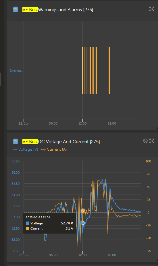
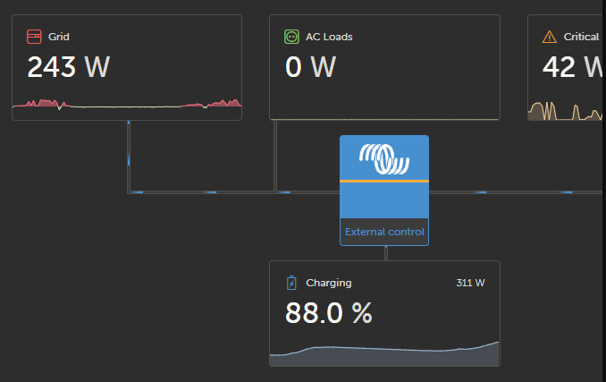
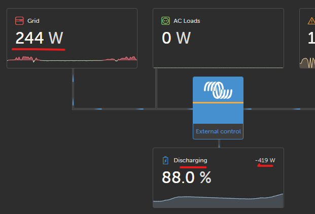
If that ‘peek’ draw is only a few kW you should not be seeing a significant voltage swing with those cable lengths. And it looks like the charger is backing out as the voltage falls, as I said earlier.
If that is the case then there is a voltage drop, that there shouldn’t be, somewhere on your system.
I don’t know enough about the internals of the Victron to comment an a mechanism that could load the grid, even briefly, to the point where the voltage falls be 25V, although that seems unlikely, even as a fault, to be occurring without tripping the 20A MCB, which, depending on its type, would probably trip between 60A and 100A within 0.5S
I do not know if the voltage drop is a symptom or a cause, with respect to the inverter, but I do know you shouldn’t be seeing one that big.
Please check for the voltage swing at several points, starting at the inverter and moving towards the main incoming connection.
Also make sure you have the positions of AC loads and the meter/s properly defined in the console setup.
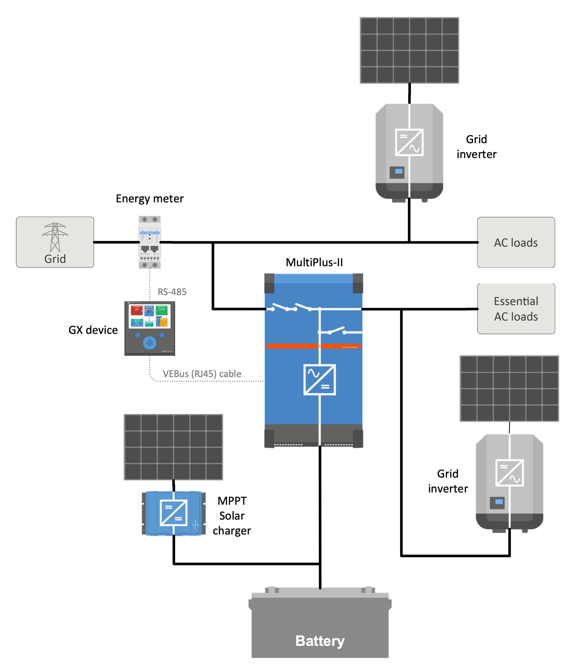
If you are able, please draw a single line diagram showing what is connected, where and with what size wire. This is not a circuit, just a drawing showing the relationship of things and their connections. Like this, but obviously not this arrangement.
Including breaker sizes and types along with cable length for anything outside of an enclosure would also be helpful. You may find it easier to give things numbers on the diagram and then provide a detail schedule, separately, to stop the diagram becoming too messy.
lastly…
Please turn off the inverter entirely and then add a significant load to the house, or a spare way in that board, a couple of 2kW electric heaters would do nicely, and observe the voltage drop.
Preferably at whatever points you measured before.
Its seems like an odd problem, I grant you.
Disclaimer… Please take my comments in context…
I am NOT a Victron expert and have no formal Victron training.
I do have two Victron systems in my house and have helped friends in the past with various setups, so I am reasonably familiar with setup and potential issues in ‘some’, but absolutely not all, circumstances.
I design and install micro hydro installations for a living and qualified as an electrician in the UK several decades ago.


