Dear Community
This thread has proven very helpful to me and I would like to say thank you to all who contributed to it.
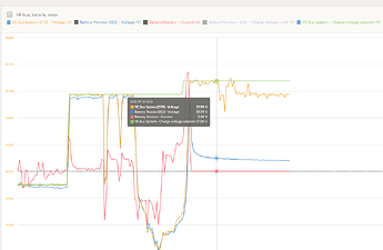
Not only did it help to get rid of the mysterious hasty discharge events right after reaching a full charge (first I thought it’s some kind of battery life algorithm), now I also know how to tackle nervous charge/discharge behavior at the top end while keeping useful DC feed-in enabled.
To make it easy for anonymous readers, here’s what I did in short that solved the problem:
- leave float enabled in your BMS (thx @dick ) , but set RCF and RFV to almost identical (3.45 and 3.44 respectively) (*)
- use VE.configure to set absorption and float voltages in the Multiplus accordingly (*)
- do not forget the same settings in your MPPT if you have any (*)
- realize that this is perfectly normal charging behavior for LFP (thx @dognose )
- be happy not to blow any fuses and keep a few % more in your battery for the night
- (disabled DC feed-in until updates will solve erratic behavior)
(*): I’m surprised to see that this is not done automatically when selecting the LFP profile
Besides I finally understand why my three JKs were never aligned with their SoC (thx @idobuiter and again @dick ). Calibration maybe also will improve things further (thanks again @idobuiter ).
This community is awesome, including the direct involvement of the manufacturer! Thank you.
Some background:
Our system here in Switzerland in our basement is running to provide nighttime energy to 8 neighbouring houses in total. It’s a new thing that we are allowed to have virtual clusters and act as one customer. (There is even just one bill that we have to split internally. Data of every smartmeter is provided for free by law for this purpose.) External control via grid setpoint, data collected with whatwatt. Peak shaving, dynamic pricing and pooling for grid stabilization are to come, but not a reality for private households just yet.
You might be surprised to hear that just three MP2 3000 (got them used) and 50 kWh are sufficient for this purpose. 95% of the time power is enough and even MP 8000s or much more capacity would just reduce grid draw by a few percent. Why? Because not everybody will cook dinner everyday or at the same time and it’s a delicate balance between enough solar yield in winter (battery fully charged in the evening, three houses with a total of 75 kWp) and limited demand in summer (battery depleted as low as possible in the morning). Both help to improve ressource efficiency and financial numbers.
Room for improvement for @dognose & team:
Oftentimes power is low (even with our cluster!) and one or two MP2 would be sufficient thanks to phase net-metering (using “total of all phases” anyway). Thus system is wasting ~500 kWh/y, even more in private systems. What about a new assistant (“eco-mode”) which sacrifices UPS but increases efficiency a lot (a thing where victron doesn’t really shine yet)?
Oh, and when we’re on it: The fact that I had to dampen the case to get rid of noisy resonances just like a car door, replace lousy fans with Noctuas (in addition to the 40kHz upgrade) and add my own rubber for mounting the multis to the wall is something I’d expect the manufacturer to have an (even better) solution for.
Other than that: Best and most flexible system available. Love the kit approach for puzzling your systems together.


