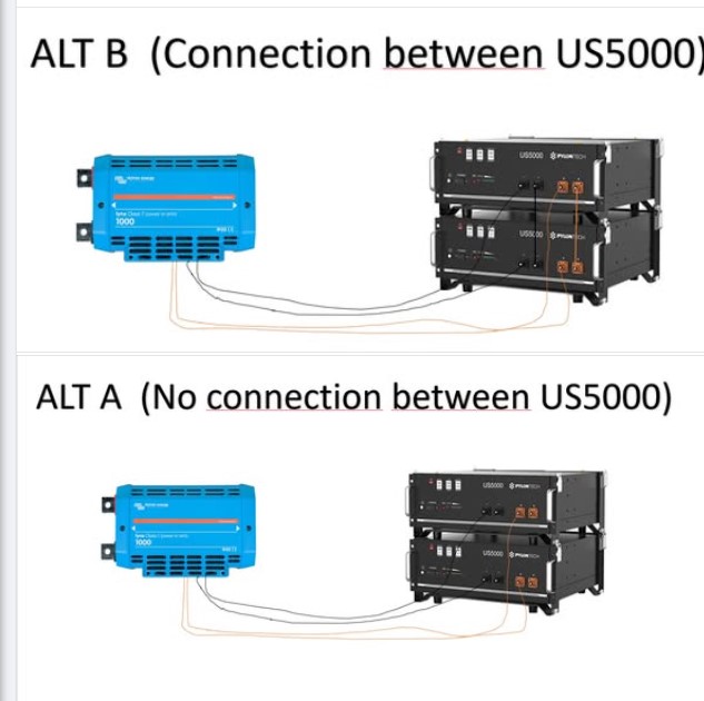
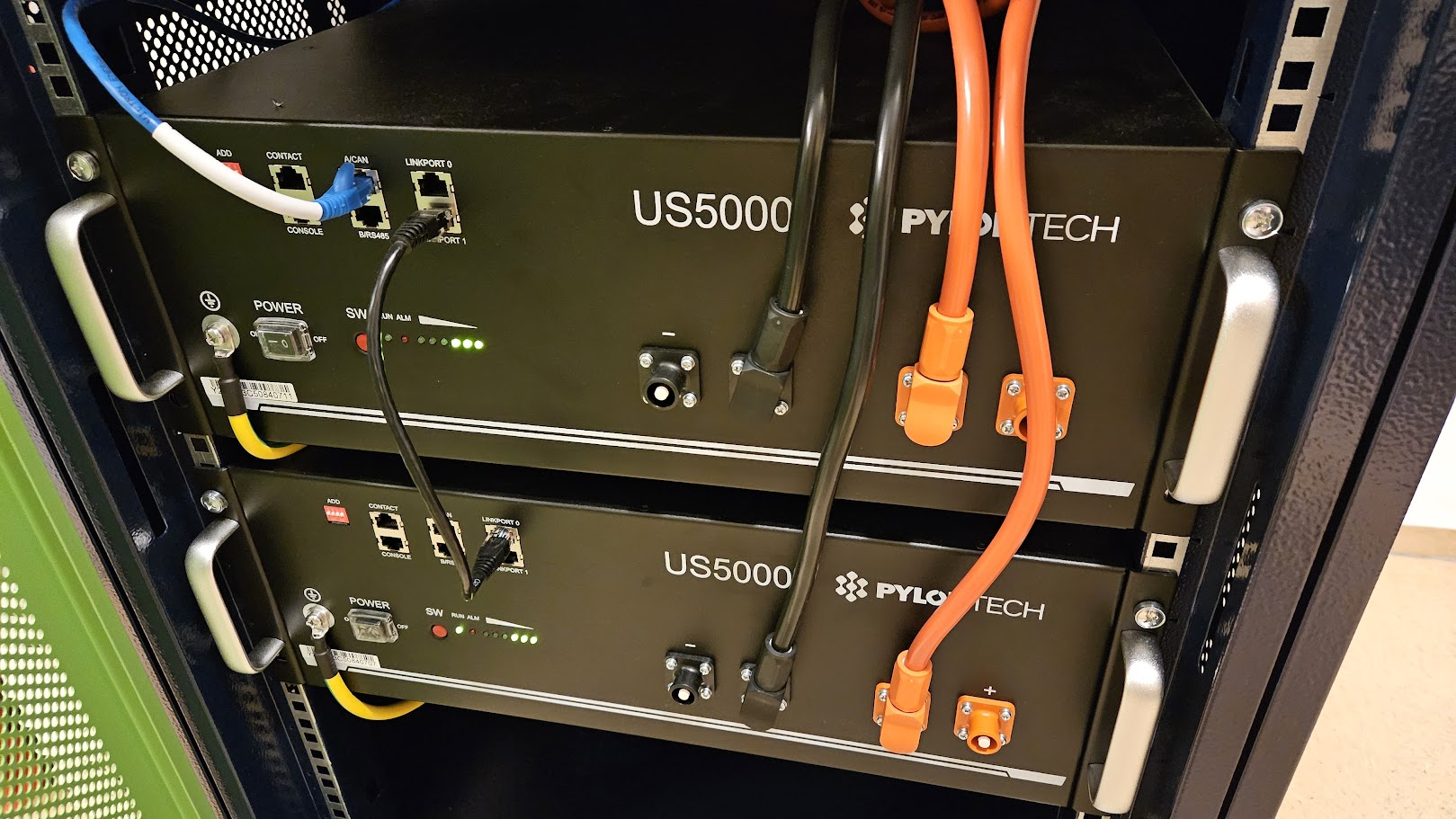
I need some help on how to connect the two Pylontech US5000 to the T-Class power in.
Alt A or B, and do I need separate T-Class fuses for each of the cables if using Alt B?
If so, can I connect one cable lug to the same bolt as the fuse, or do I need separate bus bars? I feel hat this get expensive fast. Like $150 for that fuse from my installer…
The US5000 has an internal breaker, so fused power in’s are not really needed…
Both can go to one fuse. no link connection is needed between the US5000’s if they are both wired to the fuse / busbar. Alternatively, you can link them together, and then wire only the top battery to the fuse / busbar with no loss of performance.
I personally did not want to rely 100% on the US5000 BMS as “internal breaker”. Although it might be already quite safe. Just to be on the safe side, and since you anyway have two ports on the Class-T, I spent a separate fuse per US5000 in my system and did not connect the batteries among each other.
The Class-T, for me, is only a “worst-case fatal short” fuse towards the batteries. For everything else, I rely on the PylonTech BMS and the Mega Fuses of the MPPTs/MPII.
In the future I’ll have six (or more) US5000 units. That will require three or four T-Class power-input connections, with six to eight T-Class fuses in total. It’s going to be expensive.
The purpose of these fuses is to ensure that no battery can back-feed excess power into another battery and to limit the power in the cables as specified (120A * 1.2?). (The inverters and MPPT charge controllers already have their own fuses to protect them or to isolate the main bus in case of a fault.)
To reduce costs without compromising safety, could I connect both positive cables to a single 225 A T-Class fuse—one cable on each bolt of the fuse terminal?
If I wire multiple battery pairs this way, what happens when one fuse blows? Will the other fuse then carry more current than the remaining batteries can safely supply and blow as well? In other words, what happens if the inverters draw more current than the sum of the remaining batteries can provide?
Can we detect a blown fuse some how and reduce the inverter power?
Are those 5kVA inverters? If so, the battery pack is horribly undersized. That is not great for the batteries which have a history of not lasting in that configuration.
I would encourage you to add more.
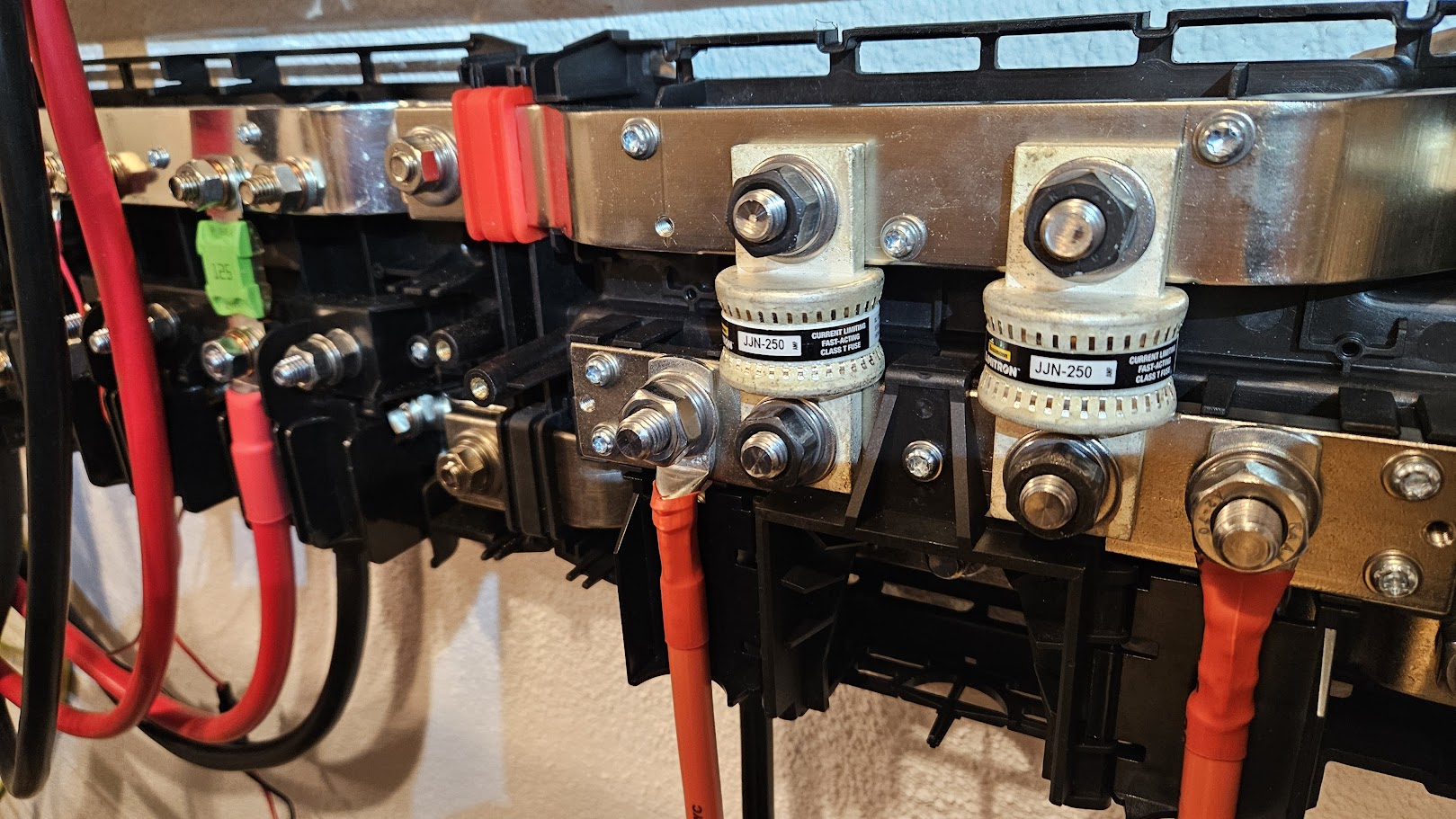
As my installer has chosen a 175A fuse for a maximim 125A rated cable, it seems a little bit off, and he has also drilled bigger holes to make it fit. Looks awfull and the fuse certification will most likely be not be valid any more.
I’m thinking that you can connect two batteries to the same T-Class fuse by mounting the other cable to the same bolt as the fuse. The cable will be on top of the fuse.
This is because I don’t want to use fuses that have been tampered with, and a 225A fuse will fit.
Do you think that is an ok solution? Should I ask Victron support?
Feeding current from one battery to another is very rare,this would require greatly different SOC, and terminal voltages. You won’t need to worry about that unless you are connecting new batteries to an existing stack: the procedure is then to equalise the voltages to within 0.5V before connecting them in parallel. The internal BMS mosfets will also limit the current to ~80A.
Yes, It’s fine to connect 2 cables to one fuse, however each cable should be abler to carry sufficient current to rupture the fuse. This is not the same as the cable’s continuous current rating.
These class T fuses would only blow if you had an inverter short, or dropped a spanner across the busbars.
Ok, but it is not. My Installer has now connected two US5000 with one standard Pylontech cable rated for 120A to a 175A T-Class fuse using the T-class lynx in.
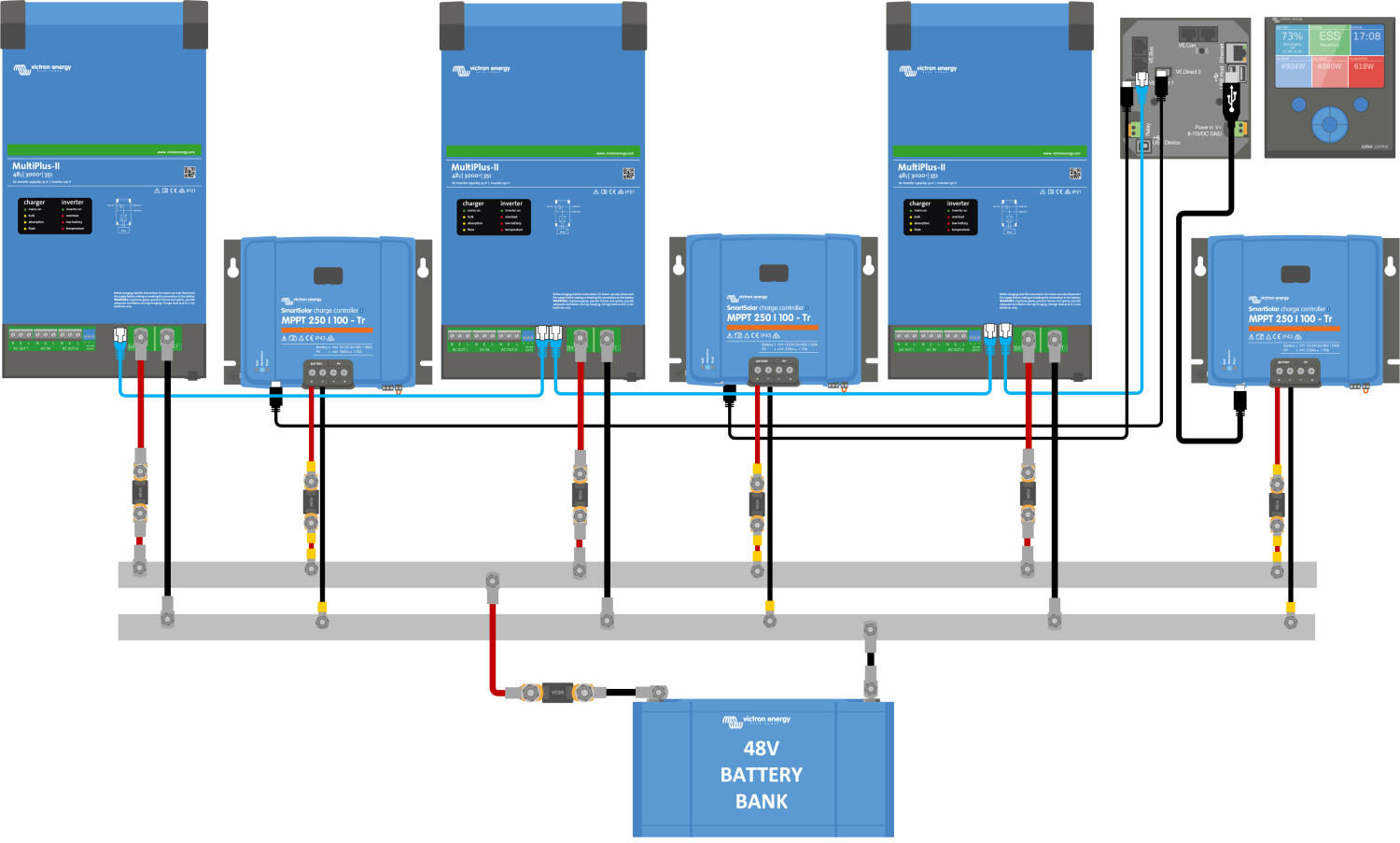
My 3-Inverters “3-phase system” are each connected to the busbar via 125A fuses in a Lynx distributor. Also, my MPPT is connected to that same Lynx distributor as the inverters.
I was thinking of connecting two US5000 to the same 225A. But with two sets of standard cables. One for each battery.
Switching to a 225A, so I don’t need to drill bigger holes in the 175A fuse. I get the shills just thinking of drilling the fuse hole bigger. Still, one cable is only rated for 120A, as you say. So that is no good idea then…
How should I do this? Use a Lynx distributor for the batteries and use 125A fuses for each battery? Then put a T-class somewhere else that can handle 10kA as specified in the Pylontech manual?
With multiple batteries, or multiple stacks of batteries, these should also be distributed onto the busbar, adjacent to the inverter take off points.
Fuses are rated to protect the cable size. In my opinion, concentrating all the current flow into one point to put a class T fuse in is not a good idea, particularly if that current can peak at over 400A. Using the Busbar as a potential equalisation system, with much lower distributed currents will give a far better result.
So, I think what you are saying is that using “Lynx Distrobutor” with fuses to protect the cables is the primary function, and that is what I should use.
So then I will switch to use the Lynx distrobutor in with 125A fuses and skip the T-Class fuse because it will just protect the bus bar from catastrophic shorts as I drop my screw driver over the bus bars…
When I Google schematics, I would say that I only found one schematic using the “T-Class in” for the US5000, which makes sense to me. All other uses the “Lynx Power In” or single fuses or no fuses.
I will draw a schematic and get OK from my installer!
Best to read Victron’s wiring unlimited and Energy unlimited books. Above schematic is by Victron, so should be approved by installer, subject to local regulations.