12/1200 Inverter - Fuses, C ratings, AH capacity, Max discharge

I’m trying to size up wiring and fusing on a small 12v 100AH LiFePO4 setup. Wiring diagram below.

a) The max current limit for the Blue Sea 12v distribution block is 100A.
edit: removed link to Blue Sea Common source MRBF fuse holder - because of spam filter

b) Am I right in assuming I should be sizing the wires to The Victron inverter for PEAK POWER (2200w) So 183.3A?
edit: removed link to Victron inverter Datasheet-Inverter-VE.Direct-250VA-1200VA-EN - because of spam filter

c) This means I should be using a 200A MRBF battery fuse and 35mm2 wiring for a run of 2 metres, right?

d) Is there any point to running a second 200A MEGA fuse to the inverter input?

e) If the inverter itself has a built-in 200A fuse, there’s a 200A MEGA fuse and a 200A MRBF at the battery, might they all pop at the same time and why not just use one?

f) Should some fuses be over sized and if so, which ones?

/// Section two - Batteries, C ratings, AH capacity and Max discharge

In the Victron documentation it says:

12/1200
Peak power 2200 W
Minimum battery cap. 150 Ah
Internal DC fuse 200 A
Fuse type BF1 - 32 V

Recommended wire sizing:
0 – 1.5m = 25 mm²
1.5 - 3m = 35 mm²

This part is a bit confusing for me. I’m struggling to understand the relationship between:

C ratings
The battery AH capacity
Max discharge limits on batteries
Victrons arbitrary statement of “The battery must be 150AH or over”

I’m trying to set up the system in such a way that I don’t go over the C rating of the battery when the inverter hit’s peak load.

I’ve read before that C ratings are a function of AH ratings. Are max discharge currents just a function of the BMS or does the AH capacity of the battery play into this?

I’ve read that LiFePO4 batteries will generally have a max discharge current tied to their AH capacity (e.g: 180AH battery will have 180A max discharge limit on the BMS) Though this seems like a dangerous assumption to make.

I can get another 180AH LiFePO4 battery that will just fit in the enclosure, however the documentation for the battery says “100A max discharge” so I’m not sure if it’ll help when the inverter is hitting peak load. (183.3A)

Can I de-rate the inverter by changing settings so it has smaller peak power? I didn’t see it in the settings but maybe using VEConfigure and a mk3 interface I can get more options?

And anecdotally I’ve read, in the context of battery sizing and inverters:
Quote: “I believe the 400ah rating is primarily for voltage drop at high load when using lead-acid batteries. If the undersized LFP can provide full power, less than 400ah is fine.”

I expect I’ve undersized the batteries massively for this install. Any help would be much appreciated. I probably should have read the inverter manual first :slight_smile:

I have always heard, and a search seems to validate, wire is typically sized for the normal current not the inrush current. FWIW, I’m looking at doing something similar with a 100ah LiFePo4 battery and a 12/1200 inverter. The 12/1200 is rated for 1000w with a peak of 2200w. that should work out to around 83A on the DC-side at normal full load. With conversion loss and inverter overhead I’d call that 100A. I’m looking at 4 AWG cables with a 125A or 150A MRBF fuse since my inrush is <1sec on the load I’m going to power and my run is very short at ~6 feet. Personally I think you can come down a bit on your components and size for 100A, but it’s always better to overbuild on these things to a certain degree. For longer runs you could size the cable to 2awg but I’d still personally be ok with smaller bus bars.

I heard that the inverters can run for a significant amount of time over their continuous rating and cables should be sized appropriately.
If somebody from Victron could comment on the matter of sizing cables for peak vs continuous that would be awesome.

I updated my diagram

Thanks for your reply

With the second battery added to go over 100ah I’d say you’re on the right track with the larger components and wire gauge. Have you considered buying one larger ah battery vs two smaller ones? I’ll be easier to keep all the cells balanced if they are managed by the same BMS. You also wouldn’t need the cables between batteries.

No, I already have the batteries. It would be nice to have a rough time frame of how often I should separate the batteries and balance them. Would it be work if I just ran them down to empty once a year or something and called that a bottom balance?

All manuals for products have fuse and cable recommendations. Use the manual. No guesswork there.

All manuals are available on the respective product pages

C ratings are the discharge current the manufacturer sized the battery with. For lithium it is less of an issue than lead acid. Lead acid because of its internal resistance a higher current draw ‘shrunk’ the battery capacity.

Lifepo4 discharge current is based on the bms chosen by the manufacturer - see their labels for this information.

This is the peak. So not the nominal - for alot of the cheaper lithiums nominal is half of peak.so look for recommended discharge on the label.

No but you can be careful what you plug in or buy a smaller VA inverter.

edit: removed link to Victron (Manual-Inverter-VE.Direct-250VA-1200VA) because of spam filter

The only mention of fuses in the manual is to say there is a replaceable 200A internal fuse in the inverter. There is no information regarding external fusing best practices so I still don’t know if I should be using a 200A MEGA with it.

The connection point on the inverter will take 35mm2 maximum so that’s what I’m going with. The question still stands though, should the calculations on wire sizing for the rest of the system assume that the inverter can use 100A, 200A or somewhere in between?

I am trying to make the system fail-safe by assuming that at any time somebody could plug in a ridiculous amount of electric kettles. It’s not just a personal system.

Any suggestions for keeping the batteries balanced or recommended time frames to individually balance them?
If I just ran them both to empty once every now and then, would that help?

I made an updated diagram but was told bus barring the batteries together would cause balancing issues and stress on the battery posts.

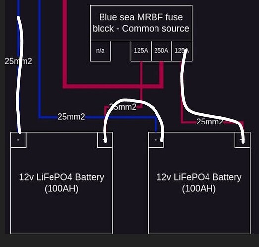
So I’ve made a final iteration of the design and incorporated a lynx power in instead of the the bus bars and fuse blocks. Please let me know what you think.

I will run 25mm2 wire from each of the batteries positive terminals to a blue sea common source MRBF fuse holder, each going through a 125A MRBF fuse then exiting the blue sea unit through a third 250A MRBF fuse.

Final design:

I think the 70mm2 might be massively going over board dependant on if the inverter uses 100A or 200A for any serious amount of time

Any comment would be much appreciated, thank you.

The inverter won’t sustain the overload for long periods.
So the 70 is probably overkill. Unless you ever plan on having max dc loads and max ac loads at the same time? Since that would be close to 240A load.
But then for that your battery bank will probably give up first.
If the batteries are individually connected to the bus bar they would do better (instead of the daisy chain.) they should balance thensleves since it is a 12v system not 24v you don’t need extra hardware.

Fuse size and type for the inverter would ideally be one that blows before the internal one. But then really is there for cable problems. In an overload the inverter will just shut down.

Thanks so much for the quick reply

We talking milliseconds at startup or 5+ minutes running a 2000w microwave?
I just can’t seem to get any clarity on how long it’ll go peak for.

Do you mind sharing the values you used to get to 240A?

For sure, that’s the weak link. I think it’d give up at a cumulative 200A because they are cheap cells that say max discharge is 100A but who knows, maybe the BMS max discharge is set to 125A/150A?
Is it particularly dangerous to be relying on the BMS as the first point of failure? How can they epicly fail? Maybe I should consider lowering the MRBF fuse vales?

I don’t understand the distinction between individually connected and daisy chaining.
I still don’t understand how balancing is different when you compare bus bars on the posts to make them parallel VS running two same length wires to a bus bar. They seem like the same thing to me.

They balance themselves because of the voltage? Or because of being in parallel as opposed to series?

Yeah for sure, I don’t want to be screwing around inside the inverter. And it makes it easier to get the system up and running again. I mean I’ve already got the lynx power in so it’s just the cost of a MEGA fuse really. I don’t know enough about fuse design to know which one would go first.

Thanks for the help I really appreciate it

Seconds. Not sustained. It allows a peak draw from a pump start or a fridge.

They will balance out in a 12v system.

Current sharing and resistance. If individuallly connected, each battery will contribute its max, where in parrallel current stacks. It can cause issues. You get to use smaller wiring and smaller fusing for each battery (important for lithium as they can release alot of fault current). If one develops a problem it is less complicated to remove for repair.

The product is designed for 1000/850W continuous at 25/40 degrees C. You should base your system design on this and not the peak, which as others mentioned, is intended to accommodate startup surges etc. If you plan running 2kW loads, you inverter is seriously undersized.

1 Like

The daisy-chain is as good as the busbar, but with less fuss. Pls don’t try to force people to pursue your fads.

Some batteries can’t current (and some even voltage) stack on their terminals.
A bus bar allows individual fusing which is technically safer this is especially important with lithium and their KA ratings.

I was merely stating best practice especially when ohms law is applied and every watt and efficiency matters.

People can do what they want. Its their kit, their money.

Where do you find such information ?

I’ve never even seen the word “stack” anywhere.

Trying to keep language simple
One example is battle born. If you wanted tonise their 12v batteries in a 24 or 48v system you had to state it on purchase or order.
There are a few 12v batteries that will state not for series use. Some even say no parrallel use or if you do a max of 2. There are components that can fail in a BMS if used in correctly, such as in higher voltage systems. (Or using them in a stack.)
It is important to research the battery you intend to use.

I realise that series usage of batteries is always a problem, but we are speaking about parallel use with busbars vs daisy chain.

And here i don’t see any problems, neither in theory nor practically.

And if a manufacturer forbids parallel use, this would apply to both wiring types.

Here’s the final design. Can anyone suggest a more appropriate size wire than 70mm2?

You have 2x25mm off each battery.
A 1x50mm would suffice.

(Although if you get really technical 2x25 actually carries more current then 1x50). Just to keep it clear as mud :wink:

Then to loads you have 1x 35 + 1x 16mm so 35+16 is 51mm. So again the 50mm should be ok on paper.

There is only one condition where i would keep it at 70mm. Is the run between the blue sea and lynx long? Or shorter that 2m? If it long then use a larger gauge.

If you do keep to the individual wiring to the bus bar from each battery - make sure they are the same length. In some cases it is more practical to daisy chain for this reason, tonnes of wiring in a small space (other than the other the ones I mentioned like individual fusing). You can undo the balanced loading and charging but not having equal lengths.
So you do need to weigh up your install conditions.

Yeah I was settling on 50mm2.

Sorry I’m a bit confused, when you say individual wiring to the bus bar, you mean from the batteries positive terminals to the MRBF fuse holder, right?

When you say daisy chaining, what do you mean?