I do not get answers from distributors on my questions.
Is my simple design in the picture a right busbar configuration? What can I do to improve it?
img20250716_21061251.pdf (157,1 KB)
Sorry but the pen paper is awful and very confusing use a proper tool to do it and you may find a better response try https://www.drawio.com/
See if this helps you: https://youtu.be/xCZEvgtnihk?si=xIxFcR7ZkkZKx04l
What are you trying to measure with the Lynx Shunt. As you have it shown at the end of the bus bar it will measure nothing. To act as a battery monitor it needs to have all the batteries on one side and all the loads & chargers on the other. Read the manual for a description of how it works.
Thanks, this indeed explains a lot. So my placement is oke, however the shunt has no function in my design. I can skip the shunt if I have 6 basengreen batteries who have their own BMS and is can bus complient with Victron?
This was indeed one of the questions. However If I place the batteries on one side and the loads on the other side, the current gets to big.
Skip the shunt, it provides no info in that location other than bus bar voltage and it is an expensive voltmeter.
What is the kWp of PV you will have on this system and can you give us some specs on the batteries? Yes current is something to look out for as the Lynx system is only rated for 1000A. Your multis will be capable of drawing around 700A from the batteries and charging them from grid at about 600A. This is fine for the Lynx so we just need to check your PV charging capapility.
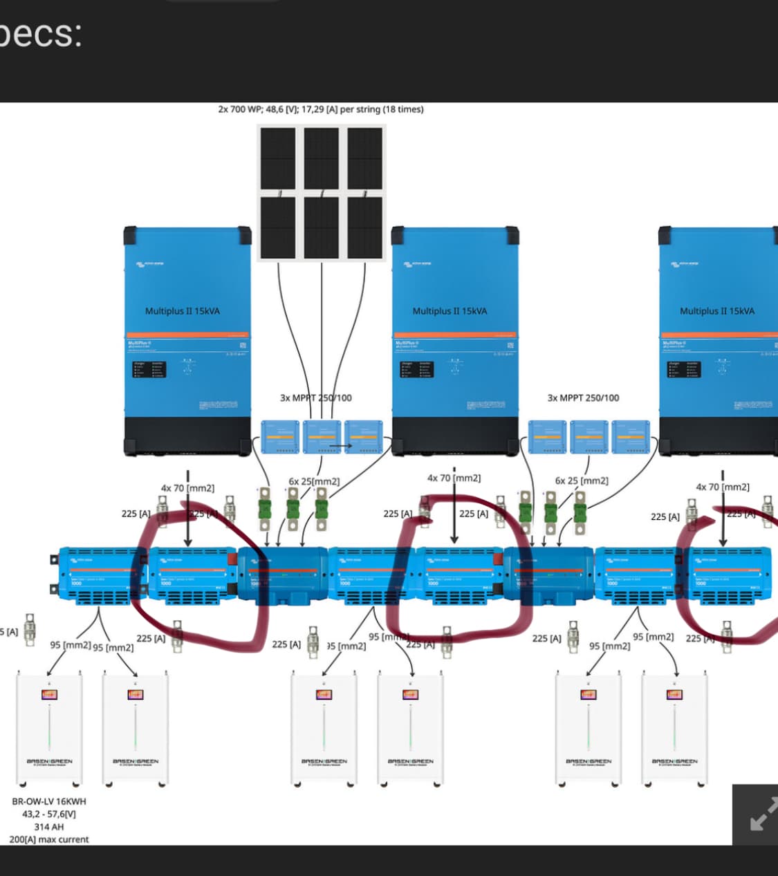
Thanks to @Daza a better picture, with all the specs:

Nice that’s what I’m talking about, but you’ve got like 8 hundred on that line, class T is the best fuse but I think you could use the Adler fuse with less equipment ie the like 5 lynx distros and the Adler fuses.
But that’s just what I would do and that should give you lower resistance because of less connections in turn saving you some money as well.
Edit I’m not sure if the Adler fuses work with the M10 so these may not work* someone might chip I. That knows or has do this mod
The M8 / M10 refer only to the end interconnect bolts, the fuse bolts are M8 in all cases for Mega fuses and the units are the same apart from this.
Correct. In my opinion it doesn’t make sense to utilize batteries that require a single shunt on large systems. The Lynx system can handle up to 500A continuous without active cooling and modifications to add ventilation. With strategic and balanced placement of batteries, sources, and loads along the buss, you can use the Lynx system for large systems without having to make custom buss bars.
Ah ok so same spacing internally that’s the part I wasn’t sure of thanks ![]()
I mine opinion the T-class power in has not only beter fuses but also can handle more heath by its design. Not looking for the cheapest solution, but for the steadiest, safest. Thanks for all your help!
It wasn’t only for the cost but you have a lot of connections due to the limitations of the Class T device so your basically fusing and already fused device ie the battery fused and to the bar to multi fused as well you’ve just increased resistance points you would be better with a power in at the multiplus bus bar point and limit the resistance by it at that point or go for the Lynx distro at that point as your batteries are already protected. Does that make sense?
Not sure If I do understand you correctly. Your text is confusing with the circles on the picture. The batteries are fused internally, The Multiplus not. So I could imagine a Lynx Power in for the batteries to lose the extra resistance (fuse) in that line. However the Multiplus should be fused, so there I need the T-class power in?
Id rather keep the fuses in place for the batteries and multis seperately, better from a regulation and maintenance point of view, id rather blow a megafuse than a class T fuse but that’s my opinion, to save cost it would probably be better to use power in for the multis but then they would be fused at the battery level, which is too high
Sorry been busy, So where the wire connects the miultiplus to the class t the one that’s circled. That class T isn’t needed and could be done with a simple mega as you’ve taken care of lithium battery issue with the Class T but where I have circled what job is that fuse doing?
As the multiplus has already been protected with the Class T at the battery, as far as I see you are protecting the cable in which case a simple Lynx distro would protect the cable, as the only thing that I think I didn’t take into account was the extra addition from the DC solar meaning you could get an overload to the cable of the multi at which point a Lynx distro would suffice.
So yeah power in out of the question but I would say Lynx distro would be the better fit you could do class t but a class t just to protect the multiplus cable for the price for something that would protect it the same way as a result of overload or for a short between the the multi and the cable. Hope that makes more sense now?