there is no manual available, and the device doesn’t works as expected.
I put a voltage divider and a Z-diode to the digital io for protection.
I have 4.1v at the input, but the node switch in node red is still off /0.
The switch is set off, so the I/O should be an input.
Please put the input and output circuit schematic to your PDF.
Please design outputs short circuit proof and inputs with optocouples like every PLC is doing this.
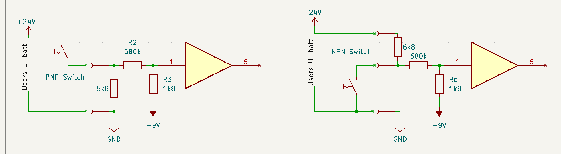
Here are my suggestions for poor mens input circuit. Variants using proximity switch PNP model what is commonly used in Europe and USA as well as NPN model used in Asia.
Main functional element is the 680k resistor to protect the input from ESD. 680k makes a voltage divider with nearly the same high impedance than any optocoupler (what is almost infinite). PCB layout should take same considerations than used for the placement of optocouples. Any mistakes in circuit and board design can be easily tested by using a ESD gun. For the existing IO Extender, Cerbo and Ekrano I bet they will fail.
Beside the ESD protection, next critical problem is to see a “clean” low level for the input. For TTL the low threshold is assumed with 0,4 Volt while the high level is up from 2,7V. Its evidend, that the low level below 0,4 Volt cannot be achieved securely by any switch or pulldown to GND. Therefore resistor R3 is used with a negative voltage. This negative voltage needs to carry only a few microampere to make a slightly negative voltage at the input buffer. Although, the RS232 negativ voltage is not very stable its typically sufficient for this purpose.
This input circuits are proven for many years and almost as good as the more expensive version with optocouples. No warranty about the values what might be adapted to 12V or 24V inputs and also depend from the available negative voltage and wether the input is TTL or 3,3V CMOS.