I have a Victron installation with a Multiplus II 5000, 3 MPPTs, a 48V ~15kWh battery, and 5000WP solar panels. Our goal is to keep the grid at 0W import/export across our 3P grid connection, and overall, this works quite well. I’m really happy with my choice for Victron.
Recently, I added an NS EV charger (along with an EV ;)), expecting to be able to charge my car directly from excess solar power. However, I ran into an issue:
The EV charger is connected 3P, and the minimum charging current appears to be 3x6A = 18A = 4140W (230V).
This is more than my Multiplus can supply (since it’s behind a 16A MCB) and more than I typically generate with solar.
When I bought the charger, I expected it could charge at 6A on 1P, but now I realize that would require rewiring it to 1P, which I’d rather avoid since I want to keep the option for faster charging.
I also do not want to charge the car from the battery , as this should not be necessary. The car can stay connected to the charger for multiple days since it is not used daily, and I want to prevent unnecessary wear on the battery .
My question:
Is there any way to make the charger use less power dynamically without rewiring it to 1P? Perhaps a setting I missed or an alternative approach to better integrate it with my system?
Replying to my own post as I continue my research.
I came across this very interesting discussion that suggests it might be possible to modify the charger to allow switching between 3P and 1P operation, which would be a game-changer. Ideally, I’d charge in 1P during the day when there’s enough solar production and then switch to 3P when grid electricity prices are low (at night).
Thank you so much for the response and for sharing this great reference! The archived forum post provides the kind of insight I need, and it gives me a direction to proceed with the conversion.
I understand that this isn’t an officially supported feature, but I appreciate the fact that the hardware was designed with future flexibility in mind. I’ll order the necessary connectors and see if I can get it to work. Once I make progress, I’ll be sure to share my findings here on the new forum for others who might be interested in this as well.
The modifications are in! I successfully implemented the 1P/3P switching using the Schneider Electric 25A contactors, following the setup described in this document by @hbraak (Heiko):
The Schneider Electric 25A (A9C20732) contactors fit, but…
Terminal size is quite small – fitting the wiring was a bit of a challenge. If I were to do it again, I might go for 35A or 40A contactors since they likely have bigger terminal holes, making the swap easier.
Next Steps:
I’ll now look for a way to make the ModBus changes from my MacBook. suggestion are welcome.
I’ll share again when I have any updates and happy to answer any questions!
I managed to change ModBus 5100 to 1, but after doing so, I immediately get Error W-102, and the option to set the Auto mode phase to “Single + 3 Phase” does not appear. The car stops charging completely.
The error message is quite strange - I can’t imagine that the grid operator (NL) is blocking the EVCS. When I set ModBus 5100 back to 0, the error disappears, and the charger starts working again.
All help is greatly appreciated! Thanks in advance.
@Lpopescu, I appreciate the functionality is not supported and may be took a bit of a gamble here with the modification. Unfortunately, I do not seem to get it to work. Is there any possibility you could give me some direction or solutions I could try?
May I ask how you have been able to change the value of modbus register 5100 or 5101 to 1?
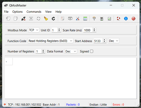
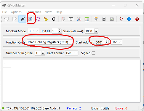
I tried doing so by using a software called QModMaster, which is mentioned in the EVCS phase switching guide by @hbraak (Heiko), but I could not get value 1 to remain set after having transferred the write-command of funtion code “write single register (0x06)”.
Am I using a wrong approach? [edit: my approch was acually right, but I had not given permission to access the modbus addresses as I had IP address whitelabeling turned on by mistake, which only allowed my GX device to R/W]
Do I need to disconnect my GX device meanwhile or what software do you suggest to modify the modbus value? [edit: the GX device does not neeed to be disconnected]
Neither setting modbus register 5100 (nor 5101) to 1 seems to “unlock” the phase switching option for me.
I get no feedback from my EVCS that any change in settings has happened at all…neither “EVCS externally blocked by grid operator” nor “internal settings changed, no support”.
When I read the modbus register after supposibly having written value 1, I always still get value 0.
Does anyone have an idea what could be the problem here?
…after a few more tries I just realized that no matter the modbus address I try to read, I always receive value “0” - so there seems to be some sort of problem regarding the access rights I believe, as most addresses sould have default numbers as listed in the VictronEnergy modbus register list.
…when I woke up the next morning it hit me: I had activated the IP address whitelabeling at the very beginning, as it is recommended by VictronEnergy. Well, it makes sense now that I was able to connect but not have rights to neither read nor write the modbus addresses. Never mind - rookie mistake!
I’ve just completet my modification using two Finder 32 A contactors - they fit nicely, as they are narrower than the 40 A contactor that they replace:
This way, we will be able to charge our EV with 32 A on a single phase (up to 7,36kW excess solar energy even with our three MultiPlus II having a max. cont. output of 4kW on each phase, but the grid meter from the operator is set to net all phases - and so is our additional smart meter EM540 - so I can technically feed in from 2 phases with 3,68kW each and consume 7,36kW from the third phase and have net 0 consumption and costs from the grid), which will give us more flexibility in case the automatic switching from 1 to 3 phase does not work as intended - and obvouisly we can also charge with 32 A in a 3 phase setup, in case our future EV will support this and the grid operator will give us permission to do so.
Now the entire current path from the circuit breaker to the EV is realized in 6 mm² - the 32 A type 2 cable with 6mm² for this setup cost us about 120 € whereas the 16 A cable which only had 1,5 mm² would have cost us about 100 €. Not a hard decision to make on my opinion.
I paid around 50 € for both contactors, shipping included, which is more than fair, I believe.
The contactors’ product name/ID is 22.72.0.230.1310, in case anyone is interested in going for this choice…
I’m really happy now with this modified hardware setup, given the high flexibility and performance, nice VRM integration and relatively low costs compared to other comparable EVCS - thanks VictronEnergy for supplying this (inofficial) feature
One small hint regarding the modbus TCP register list: the addresses have changed by +1 for me as well, so I needed to change the value of 5101 to 1 instead of 5100 in order to activate the phase switching feature - same goes for addresses 5055-59.