I’m going to install energy storage system based on Multiplus II 48/8000/110-100 (3 pieces for each phase). According to instruction I’m going to use 2x50mm2 + 2x50mm2 on DC side, and here’s the question - can I use victron battery switch, which is 1-pole (so I connect both cables to 1-pole on switch input and again 2 cables on output), or should I find other switch, which would be 2-poles. I’ve read different opinions about it. I’ve tried to find 2-poles switch, but with limited success - only ABB, which is extremely expensive. Victron diagrams show battery switch when one DC cable is used, and with 2 cables there’s no switch. What are your thoughts?
I meant Victron Battery Switch ON/OFF 275A. I don’t know about 500A. The purpose is to disconnect respective MultiPlus from DC batteries (for MultiPlus maintenance etc.)
In manual (https://www.victronenergy.com/upload/documents/MultiPlus-II_230V/32424-MultiPlus-II___Quattro-II-pdf-en.pdf) you can find in chapter 3.5 the statement “To completely de-power the inverter/charger, disconnect the DC fuse or turn off the isolation switch, DC contactor or DC circuitbreaker, located between the battery and the DC terminals of the unit.”. So I used in my previous installations Victron Battery Switch ON/OFF 275A as a DC circuitbreaker, but those were with DC single cabling. Now I’m going to install DC double cabling for the first time, and I’m not sure whether Victron Battery Switch ON/OFF 275A (which is 1-pole) is a good choice for DC circuitbreaker in this case. I found some opinions that using additional small bars would be required, but it’s a bit of overkill I think, on the other side I cannot find good and reasonably priced alternative for Victron Battery Switch, but with 2-poles on input and output. Using fuses as DC circuitbreakers is not very convenient in my opinion.
Maybe I just exaggerating and I can simply connect double cables to 1-pole of Victron switch, but I am not sure whether it can lead to any consequences.
The definitive answer is - local regulations. These will always affect design.
The only time it is not recommended to break both neg and pos in a battery system is in multi inverter systems where you do not want to break the negative between inverter units, but then to accomodate the regs for breaking both, you break it after the bus bar
If you are running cables in parallel, then you should have one switch pole for all cables (be it 2 or more) that can handle the full current.
Victron equipment requires switches and fuses in the positive cables only. Failure to do this may result in high ground currents through communication cables and interfaces, generally to their detriment.
of course, I fully understand it. My question was what kind of switch should I use for parallel cables (2x50mm2 pos). I think the one I found (link above) is ok (it is 250A, Multiplus will generate not more than 110A).
If using these important to ensure fuses selected are suitable, there’s a lot of fuse variants. Many of the fuses have ‘AC’ ratings printed on them which aren’t applicable. Most of those manufacturers issue supplementary documents advising on the DC ratings if applicable.
There are many good solutions, the technical points to watch are the dc voltage rating - must be higher than the max operating voltage, in this case a rating greater than 63V will be adequate. There are 2 important current ratings, one is the continuous /switching current (or trip current)of the device “Icn”, the other is the one time ‘bolted short’ current that the device can interrupt without destruction - this is the Icu. calculating what this Icu current in your system depends on the battery Voltage internal impedance and cable resistance. typically 6kA will suffice for this.
Local regulations such as for Australia demand isolation in both positive and negative battery cables, however, exceptions based on manufacturer’s requirements can be granted on a case by case basis.
Without knowing more of your environment (land, marine) or applicable regulations , the 275A switch with both wires on the same stud would suffice. Other requirements such as fusing, breakers, etc… may apply based on your location and environment.
Ensure the switch voltage and current ratings meet or exceed the highest values that your system may experience. The bigger the switch will make wiring easier.
Having installed Victron battery isolator switches on 70mm2 battery cables recently I think you’ll struggle to get two cables on each M10 stud. There’s not much room inside those switches. But I guess you could feed one in from the top and one from the bottom and that might work.
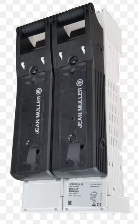
I’m going to use 2x50mm as this this recommended by Victron for my set up. I’m also going to use one pole for one cable with the switch I provided the link above (the switch poles are isolated, so in fact it is a double breaker, but I’m going to connect only pos cables to it, so it shouldn’t matter). I ordered it for tests, it should be delivered in couple of days, so I will share my experiences here with you. Price is very reasonable ~50USD, so it may be good alternative for me. Interesting fact is the switch also has MCB functionality, but I’m going to use fuses anyway, just to be on a safe side.
That looks like a handy device. Definitely easier to install on bigger cables. The Victron switches do look neat but that looks more practical and is a reasonable price.
I’ve installed both NH00 fuse disconnects and Victron battery isolator switches in series. I’m not sure how durable the disconnects are over the longer term for multiple operations, as they’re not designed for routine switching, and the Victron switches are easier to switch off in a hurry I think.
The correct way to install oversized or multiple cables to a stud terminal is to use a copper palm.
2 cables can usually be accommodated on a stud, with one lug being installed upside down, such that the relatively flat surfaces of the lugs face each other.
3 or more cables, or oversize cables need a palm, which is like a section of copper busbar, drilled to accommodate the required number of cables. This is bolted to the stud at one end, and is used to spread out the cable attachment area.
I’ve finally received breakers, but my installation got delayed, so I still don’t have much experience with it. I tried to attach the picture, but - shame on me - don’t see an option for it in editor . The quality of the breaker is acceptable for me - it is not obviously e.g. ABB level, but it is 15x cheaper… It has overcurrent protection and therefore the only question is - will it work properly with my setup (two positive connected so two currents going in the same direction), as originally I think it was designed to break circuit with one positive and one negative current. I hope two positives wont trip the protection, but I couldnt verify it yet…