I’ve continued to analyse the problem. For that I’ve simulated the behavior of the car with the CP signal using small electronics described on this schema :

extracted from this site.
When S3 is closed, it is simulating plugin of the car. When S2 is closed, it is simulating charging request ie closure of the relay. When S2 is opened, it is simulating the opening request of the relay.
With this test system, I get following results with oscilloscope:
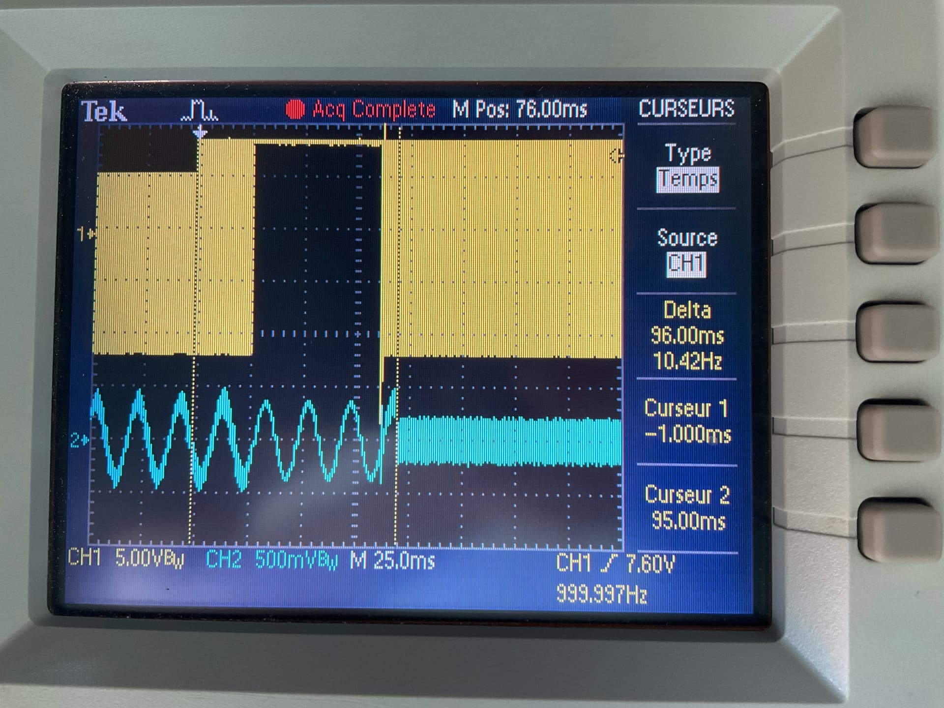
I remind: in yellow the PWM signal, in blue the 220 V get from the charge cable with a coil for safety.
We can notice that the delay for relay opening is below 100 ms, which is compliant with the IEC 61851 much shorter than the value get on request by the Zoe
We can notice also that the PWM signal disappear during around 75 ms, which is not forbidden by the IEC 61851 but has low added value and could be source of problems for some sensitive car.
So next question is : what is the difference for the EVCS between the test with the Zoe and the simulated car with resistors and diode : with the Zoe, some current is drawn.
So I add a curent transformer on the phase to display the current drawn by the zoe when the problem occur. It is the purple signal below:

We can see the current drawn by the Zoe, in purple, decreasing to zero, 1s later (T1) the relay opening request send by the car ( raising of pwm to 9V) and 2s later (T3) the opening of the relay.
We can notice that the car is “fair” and first decrease the current drawn before request relay opening to avoid sparks in the relay and to not decrease its lifetime.
The last idea is : How to trick the EVCS to mask it the current drawn by the Zoe ? It’s quite easy, just open the box, unplug the phase L1 wire from the relay, remove it from the EVCS phase L1 current transformer and replug it on the relay. The impact is that the EVCS won’t see the current drawn, won’t be able to display the power provided to the car, won’t be able to count energy etc… But it is possible to do a charge test.
On the scope we get the following result :

We can notice that the relay open around 140 ms after request provided by the car, which is a little above the IEC constraint of 100 ms, but the measure is not very accurate.
We can not see it on the picture but the Zoe charging procedure don’t fail and continue. The Zoe request again relay closure 20 s later to really proceed with charging ![]()
![]()
![]()
So the conclusion is that the EVCS delay relay opening for no real reason in this case (there is no risk of sparks into the relay as current has decrease to zero for 1s), in deviation with the IEC 61851 lead to raise an error in Zoe charger (which could think that the relay is stuck).
It is not a solution because EVCS has no interest without energy metering, this test allows to find the source of the issue. The solution could be in the firmware.
Thanks if you read me up to there.