VDC ripple improvements

Good afternoon,

VDC ripple improvements.

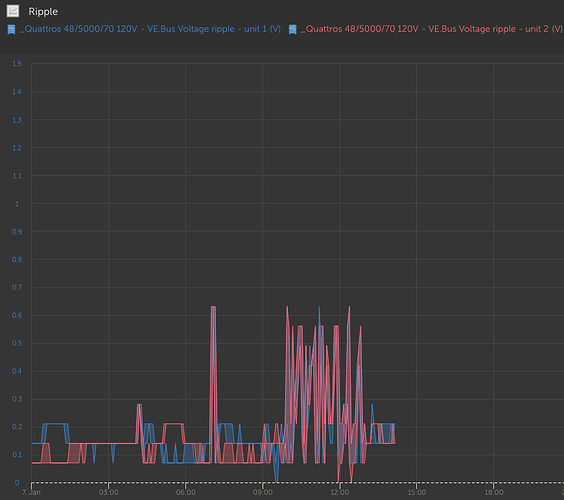
As discussed on the previous forum, the results are in about the VDC ripple improvements we made since this past half year on a 3-phase 24V 8K Quattro system with 4200AH bats.


2 graphs are captured, the first is in normal view and the second in detailed view.
Till about the 24th of June the installation was running bog standard, from then till 30 september we added on each inverter a 0.27F capacitor over the busbar, from then till now we placed 2 0.75F capacitors with a choke in between.
The result is very clear, ripple can be improved enormously.

Regards, Jeroen.
VRM Portal - Victron Energy, no password needed.

1 Like

Great job!

I’ve got dual 48V/5k Quattros (USA split phase), and decided to add a 0.1F low-ESR TDK electrolytic cap across my busbar. This reduced the rms ripple from 1.4 Vrms to 1.0 Vrms when inverting 7000W. Looks like additional caps would really knock it down.

I’m measuring peak AC ripple current through the capacitor at almost 60A.
Did you check to see that your caps can handle the large ripple current or take any measurements?

I use 3 parallel capacitors in my 48V system with ‘only’ 2 Mp2 3000 but another 2 3kw BASBA for hot water tank and air conditioning …

Works perfectly when large loads are switched on

1 Like

Hi Rick,

Thanks for the compliment.
Yes we did/do measure a lot, as this test is still running.
Over the busbar before dividing to the 2 batteries we have placed 2 Licap 18V 62F Ultracapacitors in series (24V system, 36V capacity, 32V max charging voltage) already years ago, these “boost” up to about 80A when we start heavy equipment.
This was our bog standard system for years but we noticed secondary ripples (3 phase), and a supercapacitor is not really good for that.
So, we placed first these 3 Kemet ALS71A274NT063-ND capacitors right on the busbar of each inverter with silver cables (speaker cables), these produce without load about 6-8A and when we start heavy equipment about 43-45A just for a flash second, just over the limit of 34A.
Then we mounted 2 Kemet ALS71754QT040 capacitors on the busbar to the batteries and the positive side of this busbar is cut and a IHXL1500VZEBR68M5A
mounted in between.
This since its an inverter-charger so this ripple is “handled” while inverting but also while charging, a so called CLC-circuit for 2 directions in this case.
These also use about 5-6A without load and with heavy equipment about 35-40A.
That created that the 3 other capacitors are reacting slightly less and are now also at about 35-40A when starting heavy equipment.
Under load, after start, all capacitors do 12-18A and the ripple is never higher than 0.2V.

Your TDK capacitor is from the B41xxxx-series 63V, correct, these can handle about 23-25A max, so watch out to run long time on full power as these can get very hot, also, it reduces lifetime by 5-fold or so…
I would recommend to place Kemet ALS70A334QS063 directly over the busbar connections of your inverters, this, as you have a way bigger ripple to solve than our system, these can handle 40A with ease and covering your issue.
Also, you have 48V, ours is 24V, meaning, the choice of big capacitors is limited to 63V and/or above, leaving you with the above mentioned capacitor (in stock) as I write.
But, again, 1.4Vrpp is quite high for a low amperage system, I would check cabling connections once more really good, meaning, take these loose, clean with P400 sandpaper (for prepping cars before paint), then scotch brite and then reconnect, you will be surprised what that does before investing in capacitors and chokes.

What is your VDC-loss?, between the quattro voltage sense and quattro voltage, this we monitor as well.


Here you can see the 3 inverter voltages and the voltage sense of the master, that’s our safety to monitor cable connections, etc, before things get out of hand.

Jeroen.
VRM Portal - Victron Energy, no password needed.

1 Like

Hi Steffen,

Yeah, it does, but the only thing I can say is watch out with the starting amps with single capacitors connected to solve such issue.
Victron places multiple capacitors instead a single one in their inverters, that’s not done for the capacity nor for the space (yeah, a little it is), but mainly for the amperage, a 24V 8K quattro has 26 capacitors with a total of 0.213F built in, these can handle 83.2A with ease and a similar single one just about 40A, that’s why multiple small capacitors are in an inverter.
Mostly of the time a ripple occurs is due to the battery is to small (specially Lithium), and the cable connections, and the start load to big so starting takes longer.

Jeroen.

Jeroen,
I did look at ultracaps, but putting enough of them in series to get past 51.2V was cost prohibitive for me. Also, their ESR is too high for meaningful ripple reduction. But for starting big equipment that makes total sense.

I’ve built an experimental holdup-box that I put in my rackmount setup very close to the busbars, fused with a MEGA 80A fuse using 4 AWG (21.1 mm^2) welding cable. I regret not making the box bigger to handle more capacitors in parallel, but it was just an experiment. Seeing what you’ve done, I realize getting much closer to the busbar would greatly improve the results.

I’ve only got 300 Ah total LiFePO4 rack mount batteries. In general, I find the charging ripple to be less than the inverting because I only charge at 100A maximum. If I had a bigger battery I would expect the ripple to be similar to inverting. Sounds like you’ve got sufficient capacitors in parallel to keep the ripple current down.

Yes TDK B41458B8100M000, and I worry about cutting the voltage so close, but it has a surge voltage rating of 72.5V unlike normal caps. The next step is 100V caps (no 80A) and have a lower capacitance of course. The data sheet says they can do 57A without cooling. With cooling significantly more.

When I built the setup I attempted to measure the actual resistance in milliohms through the system by cranking 150A through and measuring the voltage drop. I’ll revisit that and see if things have gone downhill.

150A drawn in these plots. Voltage drop from battery to quattros about 0.7V.
3.3 millohms from battery to quattros.

Hi Rick.

Yep, you explained your issue dead on, you are correct, due to that you only tried to “smoothen” the busbar to the battery you get these high inrush voltages as this busbar from the battery to the inverter is always “full” or resistances (very small for each single connection).
Therefore its always better to “start” with capacitors at the inverter itself and at the “entrance” of the busbar extra capacitors.
Yes, supercaps pricing went up 20% since this year.
The supercapacitor or ultracapacitor is opposite mounted, meaning, this one you put bang on the battery terminals, for extra “boost” from the battery.
In your case I would use 3 of these Licap 18V 62F Ultracapacitors (SM0062-018-P-1) in series, (we will mount these this year at another installation), with 2 200A fuses directly in between and then 2 silver cables to the terminals to connect them directly instead through fuse holders and cables (a lot less resistance again).


As you can see, these 3 can then be put right besides each other and linked.

Jeroen.

1 Like

Hi Rick.

I see your graphs now, that’s way to much resistance, example, a 500A victron shunt is 500A@50mV=0.1milli-Ohm only, you see?, I calculate that your system is almost 5milli-Ohm.
When you run for an hour just below maximum power, nothing gets 3-5 degrees higher than ambient?, or more?, must be…, these connections must be paid attention to (clean very well).
Paint the bare steel or bronze parts, red cables, transparent plastics, etc, black, as that does not reflect light so much and so you can measure more precise with a temperature gun (easiest way).
Can you show me a “detailed setting” ripple graph of when you start your heaviest load, that might give even more information.

Jeroen.

1 Like

I’ll recheck and clean the connections, but I suspect the extra Class T fuses and MEGA fuses are adding resistance I cannot avoid. I’ve put a FLIR camera on the busbars after running for a while at full load and didn’'t see any obvious hotspots, but that was over 6 months ago. I’ll give everything a thorough review sometime next week and let you know.

Thanks for the great advice on reducing resistance and proving that the ripple reduction is feasible!

Hi Rick,

You are welcome.
Yes, that can very well be the case as these 200A fuses have 0.24milli-Ohm for the 70V version.
The 32V line of Mega has 0.26milli-Ohm for 200A, so no option there.
At 200A (100%) these fuses will blow after 14400 seconds and at 200% in about 1-15 seconds.
So to reduce your ripple drastically you can try to mount temporarily 2 400A fuses, these are only 0.13milli-Ohm, this to test the other parts/connections which might have high resistance and to see if the reduction is confirm the “new” resistance.
Then, you put a blank in the fuse holders, again to test, again you get results, and these might now be very close to 0.15-0.2V ripple, then you know for sure where the resistance is/was.

Jeroen.

1 Like