This is my small system what now runs about 2 years. Here we see the upgrade modifications from a 2x3 to 3x3 Multiplus.Battery racks behind the point of view. For the moment there are 88kW DC coupled RS450 beside AC coupled Fronius Tauro. The alternating positions of RS450 source and Multiplus loads avoid currents over 800 Amp. at a single location of the 30x10 copper busbar. In future, I plan to run own microgrid together with the neighbour building what has a bigger ESS with 60kVA, 120kWp module, 600kWh LiFePo, a 20kVA gas and a 20kVA Diesel combined heating power engine.


Thanks for sharing!
What switches/fuses are between the Multipluses and busbars?
What other switches and fuses do you have in DC system?
The big white fuses are Rittal NH1, 200 Amp gGgL ordinary 3 phase AC models. At the wall in front, there is a black NH0 beside the right edge of the white NH1. Its a 160 Amp model manufactured by JeanMueller for 80V DC telecom applications. It saves about 3 Watt losses at nominal current in comparison to ordinary 160Amp NH00 gGgL.This fuse is a pre-fuse for DC distribution. You see the connected Victron smart shunt in the right corner of the room. This pre-fuse is followed by smaller normal OTO fuses as they are commonly used in RCV. Here is a link what I use for all distributors behind the JeanMueller fuse. This fuse sizes is also available with 60V DC specification (not all manufacturers and models)
The fuses are also used for power distribution to LED DC lights. As flurescent tubes are recently no more available in Europe, I go to modify the complete building for direct current LED. Its possible to use existing switches and wiring. Conversion of AC LED products is done by Meanwell NLDD1050 current sources. Further all Eltako UC impulse switches run directly at my internal 48V DC grid although they are not explicitly specified for.
MPTTs do not have fuses to the busbar as their energy is limited by the module input itself. Batteries are Pylontech (located behind the view in photo) what contain internal SMD fuses. Beside insufficient breaking capacity of the internal Pylontech SMD fuses and possibly unreliable Mosfet switching for the reason of inherent busbar inductivity, I am going to replace the pylons by my own designs for the moment. Again, this uses ordinary NH0 fuses and the Texas instruments BQ76952 BMS controller.
Some comments to the blue floor: I did not choose to fit the Victron blue what is probably RAL5012. It was choosen by one of my tenants many years ago for his pv sales office to fit the color of his vacuum tubes for sale. I can remember the controverse discussion about but in the end he prevailed with the blue color. Searching for any ink for the small inverter room with only a few square meters, I stumpled over a remaining old bucket of this material. It was expensive 2 component epoxy ink RAL5010. In the meantime I like it and maybe I am going to complete the other half of the room with the batteries with matching color.
Amazing how fast the little ones grow up.
I am wondering about the big coil of AC wire between the Multis? What is it for?
The left 3 Multis are disconnected for the moment for the reason of upgrade from 2x3 to 3x3 Multiplus. LEDs show, only 6 of the nine Multis running in the photo. The old Multi groups are wired L1,L2, L3 and second group also L1, L2, L3. If I continue this scheme to a 3rd group, efforts to equalize the AC wire length will be a disadvantage. Therefore I am going to re-wire the older Multiplus AC lines to groups L1, L1, L1 and then L2,L2,L2 and L3,L3,L3.
Impressive!
But I would seriously advise to add fuses to the MPPT’s as well. If a fault would occur WITHIN one of the MPPT’s, you really want the energy flow towards the short to stop quick fast in a hurry. Since you have 100 and some Pylontech units wanting to release about 8kA each on a short… That’s a lot of energy!

AC combiner/distributor for the 3x3 5k Multi array located right under the window from 1st photo. Box is a Hager VA24-CN 2-row cabinet similar to the ABN A24A Amigo model. Left is same model with 3 rows. Upper row is a ABB grid counter with RS485, middle row are 3 fuses for the voltage path of grid counter and 3 fuses with RCD for the 2x3 wall outlets what fill the empty space. Bottom row we see 3 current transformers model ASK by Debnar. The 5x16mmq NYM from the bottom are the primary coil and go through directly to the fuses in the middle row. Feed comes from the Multiplus IN terminal what are fused with 3x3xC32 Amp breakers in the middle box lower row.
On top are the connections for L2 and L3. As there is a window, the L1 comes from the bottom. The AC lines on top crossing the DC busbar by a bridge made from Pertinax.

As a rule of thumb (and Murphys law), cable rails and switchboard cabinets are always too small. At first approach, the system was planned with 2x3 array of 5k Multis. For the reason of thermal degradation, the 6x5kVA are only at the Multi datasheet. Number plate and certificate shows both lower and diffrent values. The produce 30kVA continiously, I recently upgraded to a 3x3 5k Multi array. The connectors used inside the AC combiner box are Hager Model KNxx assembled on KN00A Adapter to hat rail. Hager KNxx connectors have the benefit to connect 16mmq to several 4mmq wires with one component.
As the 2 rows are not symmetric in the cabinet middle, I turned complete box upside down to gain some space. Components have sufficient space at their cap rails but cables fit hardly between. There is no space to connect the sturdy 5x16mmq for ESS OUT1 why there is another auxilliary box on the right what connects 16mmq H07 to 16mmq NYM. Its a obsolete Model K9100 by Hensel-Electric.
To save more space, cable entry on the bottom is sorted diffrent from the one on top. Enlarging the images, you can read the yellow labels. They are very same than the one found on the Multiplus AC terminals completed by a incremented prename and conductor number. Labels are UNEX Model 1853-MT marked with a Edding 404.
The ESS IN C32 breakers combine the 9 Multis AC IN Terminals. The interuptable ESS OUT2 is only used for auxilliary control purposes. Therefore its fuse lin the left is only 3xB16 wired with 5x1,5NYM. Finally, there is another auxlliary fuse for the inverter room air conditioner on the very left. Its switched off for the reason of cold outside temperatures at the moment. Weather forecast expects snow again.
Assume all, it can be hardly recommended to use that small switchboard cabinets. Its a further challenge, to maintain equal cable length for the Multiplus parallel units.

Thermal Image of AC combiner/distributor. Left up is a 70mmq H01N2 feeding the Multi with about 80 Amp at this moment.
The hot spot in the left middle is a ABB grid counter with RS485. Although this counter has CT and no shunts, he contributes some losses.
Left down over the „R“ character of the FLIR logo is a 5x16mmq NYM feeding about 30kVA at this moment.
Most loses come from the 3x3xC32 Amp fuses. Busbar therefore is only 10mmq and I have to change to 16mmq in future.

We see every 3rd cable shows a little contrast on the cable bridge. This is the input line from the Multis for L2 and L3. It is 3G4 with about 4kVA each. Downside right is the same but inside a bundle of 3 cables for L1.

Hot spots upside are Multis on full operation. DC Busbar in the middle is 300mmq what conducts about 600 Amp this moment. The RS450 downside are out of operation after sunset. The 70mmq H01N2 from the RS450 have no current at all but act as a heatsink. Left side of DC bus is a self made coupler to extend the 4m busbar length.

DC busbar with DC grid taps. A few hundred watts DC load do not contribute anything to the losses with the Jean Mueller NH00 fuses. The 200 Amp NH1 fuses show moderate loses itself at about 12kW load from 3x5k Multis in total.

Victron Smart Shunt at the end of DC busbar. GND Cable on top to the right supplies Cerbo GX, a W11 PC, the PoE switch and some network stuff to run everything. GND cable on the left go to the buildings DC distributor.

Positive line DC tap with two NH00 breakers by Jean Mueller. The concept follows the Victron Multiplus AC outputs using OUT1 for essential and OUT2 for interruptable loads. The right NH00 breaker is „essential“ for the Cerbo and other controls. The left one is 160 Amp NH00 switched separate for the DC grid. It was inspired by Meanwells „DC house“ concept and uses its components. As this post is already too long, probably more about the my Meanwell DC grid in a later post.

I am sorry to say but there’s probably too much cable in the tray, have you done any calculations of that ?
You are correct. There was no calculation, only my estimates. Its a further challenge to match the cable length of Multiplus parallel units. To store this additional length inside loops makes all calculations wrong.
In the meantime I rewired everything. The 2x3 array was arranged L1, L2, L3 plus parallel L1, L2, L3. To add more power using 3 additional Multiplus, I changed the positions to L1,L1,L1 plus L2,L2,L2 plus L3, L3, L3. All parallel units are now side by side and AC length between the conductors is allowed to be diffrent. This saved about 30% of existing length and the covers of all rails fit now easily.
I am pointing at a possible hotspot in the middle of the bundle of cables. if it is getting hot enough isolation can melt (that starts at 80c with most cabling). there are charts for calculations of max. cables in a cable tray.
And it is a good practice to sepparate DC, AC and data cabling from each other, you do not want the induction of the AC on the DC wiring in any case…?
FLIR images can make it look worse than it really is, it is the scale that matters.
You can pin point the actual temp in that zone.
Wiring always heats up, the more wires the greater the heat, it is unavoidable for the most part, but as long as they are within tolerances it isn’t overly concerning.
There is always compromise in a design, determined by the environment it is installed in.
Only in ![]()
![]()
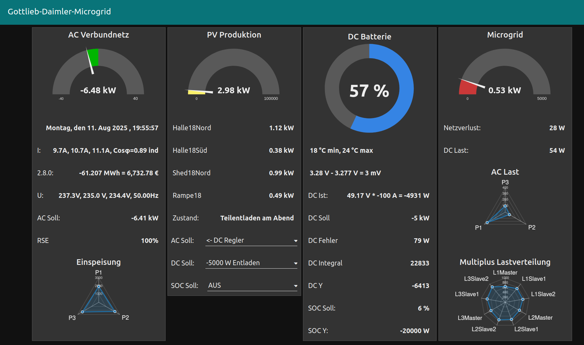
Here is a video from the MP2 ESS artwork in movement. At high loads, the shape is almost a circle for equal load distribution. At very low loads, the Ubuntu radar charts (found in deprecated Node Red V1 dashboard only) creates almost random movement of creative shapes in motion. Here is a MP4 video. For the reason of compressed frame rates, the moves are not that smooth than in the original dashboard display.
Nice installation you have there!
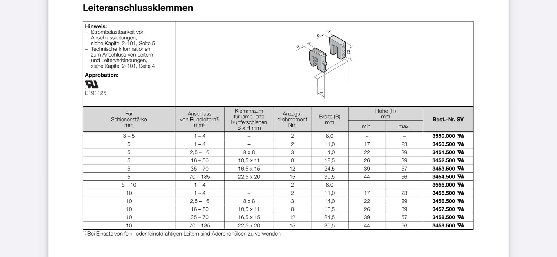
The Rail Clamps, unfortunately i cant read the types on them from the pics.
Would you share the types you have used?
I have ordered some 4m 30x10mm Rail tinned and i am not sure what clamps to use, there are so many to choose from.
The extra components that you use for the Power Visualization, are these the Ziehl IP units in the pictures?
It is Rittal order No SV 9340.030 , purchase carefull, one plastic bag contains 4 pcs. Some dealers sell a bag as one piece. Material is high temperature glas reinforced plastics. There is also a 3 phase version SV 9340.000.
Here are the Rittal numbers for the connectors
Ziehl Units UFR 1002 IP and EFR 4001 IP. The EFR model is now deprecated. New production is EFR4002IP, works with 10kV without neutral but more expensive. Both units are scanned using Modbus TCP to display its values in my own Node Red dashboard. Installation also has AC coupled Fronius Symo parallel to ESS-AC-in what are taken into account.
You are very well organized! Thank you for the very detailed answer.
It looks like a really big project over there nice to see such developments.
The missing insulation for my 30x10 flat copper busbars was no problem up on today. There is a two compenent PVC insulation by Rittal available. Order number is SV3092.000. The problem is the price what is about 15 €/m. Minimum quantity is 10m why I hesitated for a long time with any insulation.
As a replacement, I now tried a ordinary PVC mini truncing (cable routing duct). The dimension is 20x35 what fits perfectly to the 10x30 busbars. I payed 1,72 Eur/m for OBO order number WDK20035RW. Hager Tehalit is LF2003507035 but possibly not available abroad. The Unex sizes do not fit.

What problem occurred?
And thanks again for sharing your found solution.
was no problem up on today.