When designing the system, I did not read the Multiplus manual in sufficient detail to notice the recommendation for 70mm2 DC cabling, so I sized the cables and the MCB for the nominal DC currents. It turns out that there are surprisingly large AC ripple currents on the DC cabling so the RMS current is much higher than the nominal current. You need to be aware of this when designing, otherwise things end up underspecced.
Here is a pic showing the DC-side current (blue) and the AC voltage (red). The current was about 82A nominal, but as you can see it’s actually got over 80A of ripple too (at 100Hz), giving an RMS current of about 105A.

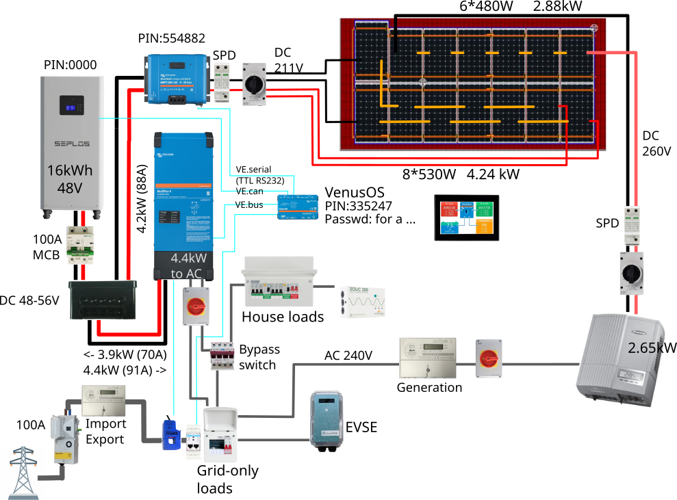
System:
So the design current (4.4kW at nominal 48V) was 91A. 35mm2 cable is rated for 245A so that seemed fine, and also the MPPT terminals max out at 35mm2. However the measured current at 4.3kW (52.6V) was 82A DC, and 67A AC, giving an overall RMS current of 106A (quite a lot more than 91A!)
Given that design current a 100A givenergy MCB as a backup battery cable protection/isolator seemed appropriate. However, given the real RMS current of 106A, that (unsurprisingly) tripped after 28mins.
After 1.5 hours at ~4.2kW the breaker got up to 54C, and the cabling 39C, which is rather too toasty. I calculate a voltage drop of 0.57V and a power loss of about 60W. The voltage drop was measured at 0.5V, so that’s confirmed.
The Wiring Guide does talk about ripple voltages, but I understood that to be saying that if the wires were too thin ripple voltages could be too high, when the actual issue is that the operation of the inverter generates large ripple currents, and the wires+ancilliaries have to be sized to accommodate them. It could be clearer IMHO.
My cables are 4.5m from MPII to battery, so that’s ~0.65V drop over the 9m loop at122A RMS (max 5kW discharge) and 80W (1.5%) heating loss.
Section 4.3 in the MPII manual ([4. Installation]) recommends 70mm2 for 0-5m cables and 120mm2 for 5-10m. How are these numbers arrived at? (That does mean 70mm2 for my 4.5m cables (i.e. 9m loop), right? 120mm2 (the recommendation for 5-10m) seems bonkers). 35mm2 is already well within the ‘<2.5% voltage drop’, and the ripple voltage pre-alarm limit of 3V. Doubling up those cables would change voltage drop to 0.32V, and halve power loss to 40W.
The Victron toolkit app says 50V DC @122A over 9m causes 2.7% voltage drop in 35mm2, 1.4% in 70mm2, which is nearly twice as much as I calculated. Can anyone explain that discrepancy (does the toolkit use total wire length or one-way wire lengths?)
Ah, the Wiring guide, section 4 DC wiring uses a voltage drop of 0.259V to produce a table of current limits for a given cable. That gives only 53A for 35mm2 over 9m, and 109A for 70mm2 over 9m. Not clear if those are nominal DC A or RMS A? And where does that 0.259V come from? It seems a little arbitrary, but presumably there is a reason? Is this 0.259V the way that the recommended cable sizes are derived? Why this voltage?
It also has a section on Ripple Voltage (section 2), but that’s largely talked about in voltage terms/limits, not current. I’ve not seen any ripple voltage alarms so that appears to be within spec. Measuring the AC RMS voltage at the inverter I get 109.4V, and 110.7V at the battery end at 4.4kW (94A) discharge. Is that high, or expected? I am not getting any ripple voltage alarms.
Adding a 2nd 35mm2 cable would be £78, replacing with 70mm2 cable would be £162 (copper is expensive!). In simple cable-losses terms this would save about £15/yr. Is there also a gain in inverter efficiency, or any other considerations? A 10-year payback seems marginal. Annoyingly there are two holes through a brick wall which won’t quite fit a 2nd 35mm2 cable, so the cheaper option would require removing the inverter and drilling more/bigger holes.
So, what is the correct procedure for sizing cables? I have a 3-legged star topology with the MPPT (250/70) on one arm, the MPII inverter/charger on another, and the battery on a 3rd. Each of these legs has different peak load considerations.
- MPPT arm. 35mm2 terminals. No ripple currents. 70A max current. So 35mm2 cable is fine.
- Battery arm. Batt peak possible current is 180A. But max load limited by inverter out (5KVA, ~91A) and MPPT in (70A) (but those cannot be additive, right, only subtractive if both running at once?). Do I need to consider inverter (MP2 48/5000) momentary peak power of 9kW? I presume only steady current of nominal 5kW, which at low battery voltage could be 96A, except with ripple it’s really 122A RMS. 35mm2 (240A spec, or 162A according to Eland cables spec) should be fine, but are getting a bit warm. The MPII manual says 70mm2. Not entirely clear why.
- Inverter arm. Is this just the same as the battery arm, or different?
What fuse sizes should be on these arms?
So I’m a bit confused about all this now. I should probably just go buy some 70mm2 cable and a pair of busbars to connect it up, but I’d like to understand how things are calculated first. It would also be good to know if these ripple currents are typical.
Everything is working OK at the moment now I’ve removed the underspecced MCB. The cabling gets a bit warmer than is ideal, but not enough to worry about.

