I’m soon going to build my first electrical system for my campervan.
I’ve spent some time drawing up a proper schematic and I’m looking for someone to check if I’ve made a big mistake.
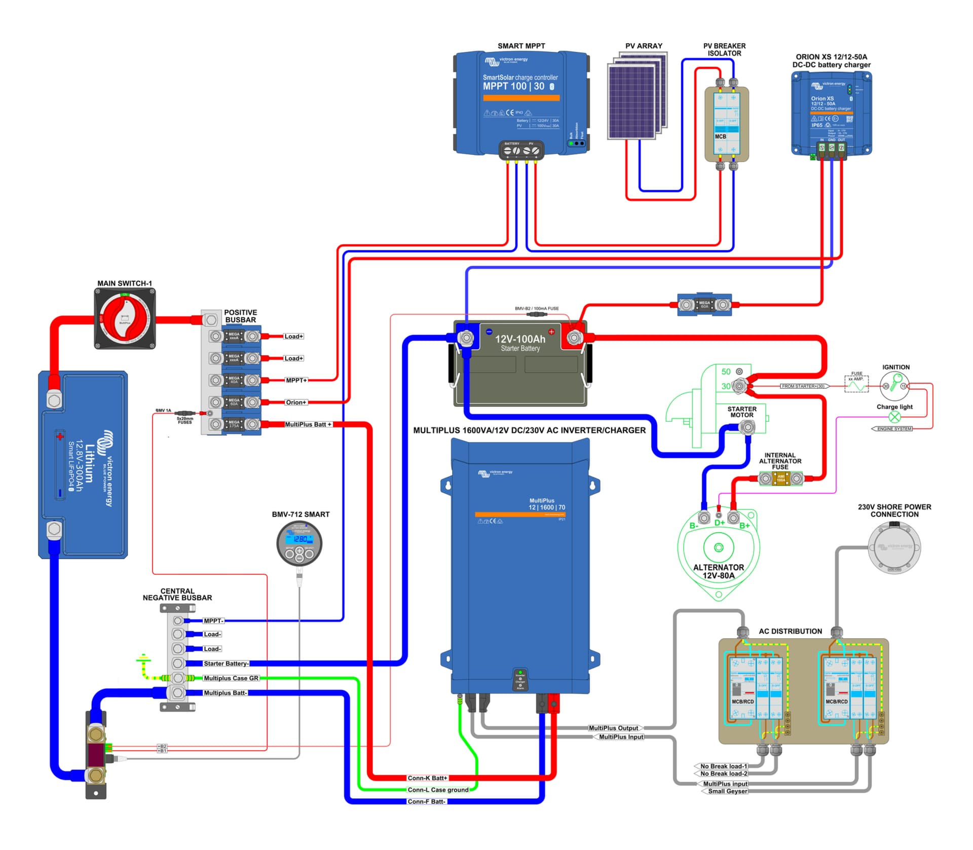
“For clarity, the battery in the diagram is a Victron, but it will ultimately be another brand. I don’t know which one yet, but it’s definitely a 300Ah lithium.”
It looms like you have done your research and the system looks good.
A few minor comments, you should have a master fuse on the battery positive close to the battery terminal to protect the wire and master switch feeding the positive bus bar.
No BMS shown so I assume you will be using a battery with a built in BMS. Some of these have a current limit that shuts the BMS down when the master switch is turned on due to the inrush current to the capacitors on the chargers and inverter. Make sure you have a precharge resistor or start the engine before turning the master switch on so the Orion precharges the system.
If your battery has a max rating of 200A then I suggest a 250A fuse and wiring and master switch to suit 250A. It is best to have the fuse 25% higher than max continuous current.
An MRBF fuse is really good for the battery. They go directly on the terminal, which deletes one cable, and you dont need to mount a fuse holder. I use them on all mine, they also dont heat up.
Very nice schematics!
I did not find any other issue (besides the already mentioned fuse)
Regarding the pre-charge resistor, - I would add a fix installed pre-charge resistor (10 Ohm, 10W) with a push-button in parallel to the main battery switch. Maybe you want to remove the battery during winter, or you have other use cases, and then the handling with is so much easier.
I did install such circuits in the meanwhile on every battery I have.
After some research, I have a better understanding of this inrush current.
I have two questions:
First, I read that you can use a light bulb instead of a resistor, which gives me an indication based on the light intensity. Is this correct? A 10W bulb? I appreciate the visual confirmation
Second question: pwfarnell told me in this topic that my Orion can precharge the system when the engine is started. I tried to verify this information online (I like to have multiple confirmations), but I couldn’t find anything about it. Could someone confirm this for me?
Precharging from another 12V source such as mppt or DC to DC charger is commonly recommended. Using an mppt is more common if you search for that because solar is more common than DC to DC.
The problem with the MPPT pre-charge is, that the MPPT controller will not run when the battery is not connected. Or am I wrong here?
And even if this would work, then you have to have sunlight… this is 50% of the day not given , often such vehicles are parked/stored in a garage or barn with no ligth…
Anyway, - regarding the first question from @frozenstars512:
Yes, a light bulb is also fine as resistance. The bulb will indicate through a very short “flash” that current was flowing and will, in best case, glow very little afterwards.
The timing normaly is like few millisecond inrush current and that’s it.
So if you take a resistor, and bush the button for 2,3 or 4 seconds, then connect the main switch, all is good. But yes, a 10W bulb will also work and reduce the inrush current to a absolut safe level.
Check whether your Multiplus has a second charger, for use with the engine start battery. If so, delete the Orion.
Lithium batteries are voracious and can cause damage to an alternator through overheating. An external alternator regulator with a temperature sensor for the alternator is a solution, but given this is a van and not a boat, you might choose to carry a spare alternator as a quick fix. If choosing a regulator, look at the Arco Zeus.
Thank you all for the pertinent information. I had trouble finding out anything about this problem initially; even the Simplex rep did not provide me with any clues.
I’ve decided to add a parallel DC circuit to the inverter with a 7 omh, 50W resistor. Also on this circuit I’m planning to add a time delay relay, which in turn will activate an added relay in the inverter DC power circuit. If it goes according to plan, the delay relay will provide sufficient time to pre-charge the inverter capacitors before the full DC power circuit kicks in. Parts are expected Saturday, so I’ll find out soon.
Thanks again for pointing me in the right direction.
Just to be precise:
This “delay relay” or “button switch” should be place in parallel to the main positive circuit breaker.
It shall connect the postive voltage to the system with a current limiting component (resistor, bulb) to prevent high inrush currents and defects on contacts/terminals, especially of the switch.
Hello, make sure that the connection of the mppt convertor to the battery is big enough. Alltough the current is not so very high, you have a voltage drop over this connection. The mppt convertor switches of at a certain level, but due to this drop it can be to early and the battery is not 100% loaded. I have used for a 75/ 15 loader a 6 mm2 cable, because the 2.5 was to small.