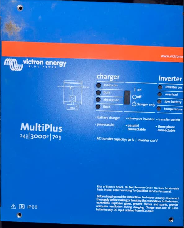
I currently have a Multiplus 24v/3000/70amp. I understand a multipus II would be optimal for my situation, but I don’t have that. My Gen has L1 and L2 on split phase. The multiplus only has L1 for AC input. Can or should I go from my Gen through an autotransformer to step the current to single phase for my multiplus, and let the multiplus break it back out to split phase for the AC Outputs? When it has L1 and L2 outputs, I sure wish I had the same for input…. (multiplus II, I know) I just want to know if doing it this way from split phase, down to single phase, and then back to split phase before my load is possible or advised?
If the gen has no other loads, and IF the center is grounded, then isolate the ground, carry out in insulation test on the winding. If good, then move the earth to L2, treat this as the ‘Neutral’ connection, L1 as the ‘Live’ and ignore the generator’s center tap (old N connection).
If there are other loads, or it is not possible to move the gen earth from the center, then use an isolating transformer, with L1/L2 form the gen on the input, and the output configured as a single phase 240V connection.
If there are no other loads, and there is no earth connection to the generator winding, then there is no issue with connecting L2 to the N terminal of the Multi.
So if there is no Earth connection on the winding, I can treat the N input on the multiplus as if it were L2?
And should Gen N be connected to Gen Ground but not fed into N on the Autotransformer?
No. IF there is no earth on the gen winding, and you connect L2 to the N terminal on the Multiplus, then the Gen ‘N’ connection should not be used. Gen Ground ‘Chassis’ connection should be connected to the MP earth / chassis connection.
for protection, still use a double pole circuit breaker (L and N) for the connection to the generator.
The Gen ‘N’ terminal will be running at 120V with respect to (WRT) ground, and L1 at 240V WRT ground.
So I am finally getting back to this project. Here is a diagram of how I am wiring it. I only hooked up wires as far as the Multiplus and plugged into shore power just to test and see if all was working well. As soon as I flip the breaker on between the auto transfer switch and the Multiplus it trips my surge protector. I have the switch on the Multiplus in the OFF position. I have L1 going to L1 AC in, and L2 is feeding the N position on the Multiplus. I am not using the N coming from my autotransfer switch. Why is this tripping my surge protector? Does the Multiplus bond N and G internally and it is tripping like a GCFI would? And second question is, is this in the order you would wire it? When looking on the autotransformer schematics on Victrons site they show the order of the power source, Multi or Quattro, Auto transformer, and then the load. So I was trying to do it like that.

In the “off position the Multi will not connect the N and G terminals to each other. When the inverter is in invert mode, N and G are connected internally, for the AC out ports only. As the inverter switches into charger mode, these are briefly connected on the AC in, as the AC in connects before the N-G connection is released.
I would also try disconnecting the N terminal of the generator, and just connect the L1/L2. do not disconnect the PE / Ground connection from the frame of the generator, or if you don’t have that, install it.
Personally, I would not install anything other than a standard TM breaker between the incoming AC and the Multiplus, or install a recognised over/undervoltage relay. Surge limiters or GFI devices should not be installed on the input side, but only on the output side..
Also, don’t turn on the inverter without a battery connection.
The surge protector is technically on the output of the shore power, to protect the complete RV from any surge. The GEN does not go through the surge protector if you look at my drawing. I should have been more clear before, I am not running my gen right now, only plugged into shore power. When I ohm out on the MP, there is some continuity between L1 and N. Is that correct? I believe the continiuity between the 2 phases wired in this manner is what is tripping the surge protector. Even if I was to pull the surge protector out, I still don’t think I want continuity between what is technically L1 and L2. Thoughts?
There will be some load on this circuit, due to the AC in measuring setup. This should be quite a high resistance. If you are having input problems, then it may be worth considering an input isolating transformer, this will also give you the option of using 120V ‘shore power’.
I should have been more clear. With all wires disconnected from the MP there is continuity between L1 and N. I guess I want to stick with 240V input if I can, both 50A shore power and my gen provide 240V. I wonder some days if just breaking down and getting a MP2 is what will eventually happen. I was just hoping not to being Victron info says I can use 240 input on the MP1.
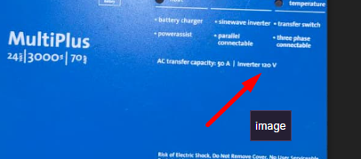
is your multiplus a 120 or 240V model?
I’ve got a AC alternator with outputs 115 - 0 - 115. I fed the two 115 legs into an isolation transformer, disregarding the centre tapped 0, and then on the outputs I have a N grounded to earth and a Live at 230v.
I’ve questioned using my autotransformer for this. If I understand the manual correctly I could feed both L1 and L2 120v to the autotransformer, Come out of that and feed one line @240V to the Multiplus. But I am not sure if you feed one 240V line to the MP I know it would split and send L1 and L2 out, but does it split that back down to 120V for each line to my system….? Just seemed like a long way around to make that happen. I was hoping to go MP first, and then balance the legs with the AT after that.
You have a 120v MultiPlus, do not connect 240v to it.
Editing to add: also worth noting that it does not have L1 and L2 outputs (reading back to your original post). It has AC-Out 1 and AC-Out 2, which is a different thing.
Please study the user and installation manuals for the unit prior to embarking on any installation path; you can find the manuals here: https://www.victronenergy.com/technical-support?product_id=147