If I connect an isolated battery, ex. a bank of AA batteries, 1.5v x 9 for 13.5VDC, in the follow manner, is this going to work as I am thinking?
the (-)negative of AA battery bank is connected to the MINUS of the SmartShunt.
the (+)positve of the AA battery bank is connected to the SmartShunt Red Wire marked as VBatt+. (but I’m also putting a diode to block any reverse current going into the AA battery bank (13.5 - 0.7 = ~12.8VDC powering the SmartShunt).
the “charging wire” that is connected to the alternator, is connected to the LOAD terminal of the SmartShunt.
a wire from the MINUS of the SmartShunt is connected to the (positive) of the vehicle/car battery.
So, in effect, I have inserted the SmartShunt into the charging wire that normally runs directly from the alternator to the POSITIVE terminal of the vehicle/car battery.
But I’ve also powered the ShartShunt from a separate isolated DC power supply.
Is this going to work correctly to allow me to monitor the charge current between the alternator and the vehicle/car battery?
Any voltage the SmartShunt is going to report will be the AA battery bank, but the current measured and shown is going to be the alternator current… correct?
note: the Aux connector and the VE Connect lines are not going to be connected to the vehicle battery, or the vehicle ground, either directly or through a tempuratute/sensor connection, to help keep isolation.
edit: post went up before I’d finished correcting grammar, etc.
It is an interesting idea, I can understand where you are coming from on this. The battery + and alternator connections may need reversing to get the correct direction of current flow. It would work from a theoretical point of view but I am not going to say it will definitely work try st your own risk.
However, you must not connect the VE Direct cable to a GX device as the voltages will be wrong and you will blow something. You would only be able to monitor it by Bluetooth. I think you understand this.
Why would you not just put the SmartShunt into the alternator ground path as designed?
Editing to add: an alternator cannot charge a battery that’s isolated from it. DC requires a complete circuit, so if a second battery is installed, intended for charging from the alternator, the second battery must share a common negative return path with the alternator.
If you want to charge an isolated battery, you need an isolated charger like an Orion-Tr Smart Isolated DC-DC charger, that’s connected between both batteries. Then, if you want to monitor the charge current going in to the second (isolated) battery, you install a SmartShunt on the negative return wire between the Orion and second battery (to monitor current going into the second battery) or between the first battery and the Orion (to measure the current being drawn from the first battery, supplied by the alternator).
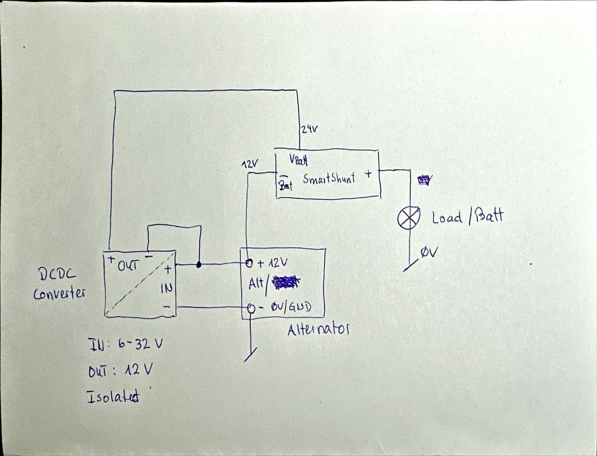
The problem is not operating an isolated battery, but rather that in almost all Euro 6 vehicles, such as the Fiat Ducato 8, etc., the ground of the alternator is connected directly to the alternator housing. This means that there is no ground connection that is not isolated from the alternator housing, and accordingly, this ground is also connected to the vehicle ground via the metal bracket. This makes it impossible to operate the Victron SmartShunt between the alternator ground and the vehicle ground as specified.
Only the positive connection can be used for this purpose.
I would now like to connect the SmartShunt to the positive terminal of the alternator, as shown in the diagram, and draw the operating voltage of the SmartShunt via an isolated DC-DC converter with 12V voltage. The 12V from the alternator is therefore the “ground connection” for the SmartShunt, and the VBatt supply must then be 12V higher than this ground connection. I achieve this with the DC-DC converter.
I will not connect the VE-direct to the Cerbo later due to the 12V power supply shift, but will use the isolated USB-VE.direct adapter for this purpose.
Has anyone done this before or has experience with a similar solution?
Has anyone actually followed through and tried one of the above mentioned approaches (or some other approach) of placing a SmartShunt inline with the positive side of an alternator output utilizing an isolated power supply to power the SmartShunt itself?