In a 24v service lead acid battery bank made of 6 volt batteries in series parallel, the smart shunt is connected to the last minus stud.
What setting do I need? 24volt and total bank amp? Or the shunt gives info of the last 6v battery?
You can’t set the voltage.
What you do need to do is make sure the positive is now on the most positive terminal.
The shunt goes between the last batteries minus connection going to the loads / charger and the positive wire goes to the first battery positive so it reads 24V. You could use the aux wire to read the 12V mid point. For the battery capacity, I will use an example. If you have 3 batteries in parallel and 4 in series of 150Ah and 6V each the system is 24V (4 x 6V = 24V, which you know anyway) and the capacity is 3 x 150Ah = 450Ah, which is what you put into the settings for the shunt.
See Section 3.5.2 in the manual.
2 Likes
Hi, your answer came up in my search for guidance to install a Victron smart shunt in my sprinter van. The set up is somewhat similar to what is described above. I have eight 6v AGM batteries configured as two parallel 24v banks of four in series. Two of the eight batteries are in the engine compartment, and 6 are in the rear of the van. Also complicating the setup is there is a battery equalizer. I’m trying to figure out the best place to install the shunt to monitor the entire capacity. Attached is the wiring diagram for the system. Thanks in advance for any advice.
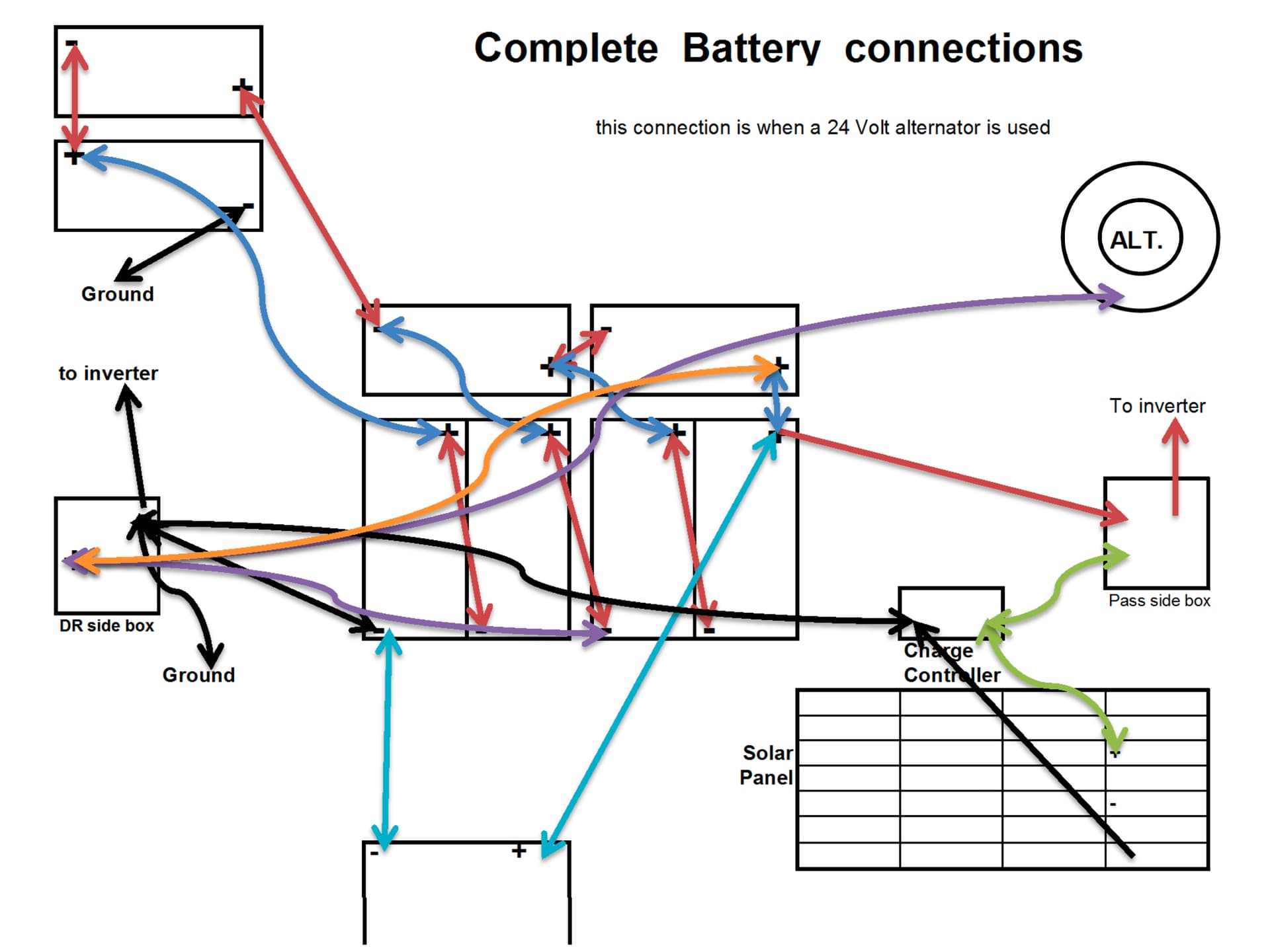
I can npt edit your sketch at the moment but a text description is below, you could update your drawing and ask for that to be chevked. The drawing below shows how a shunt is connected.

It shows a single battery but this could be a series parallel bank like yours BUT both parallel strings need to come to a common negative. Using ground to connect them is not workable.
You have to remove the ground wire from the 2 engine bay batteries and connect the negative from these to the negative of the batteries in the rear. Then cut the cable from the rear battery negative to the DR side box and install the shunt in there. You show a blue cable from the rear battery negative to a box at the bottom of the drawing, this cable needs to move from the battery negative to the negative on the DR side box. Then all negative battery current flows through the shunt.
Thanks for your quick reply. I’ll try to edit the drawing tonight or tomorrow AM (US west coast time zone) and run it by you for comment/correction. The blue lines are (I believe, according to the installer) the connections to the battery equalizer which is installed at about the middle of the van. Would moving this cable to the DR box disrupt the battery equalizer functionality?
Edit - I was able to hack up the drawing with what I think were your suggestions, attached:
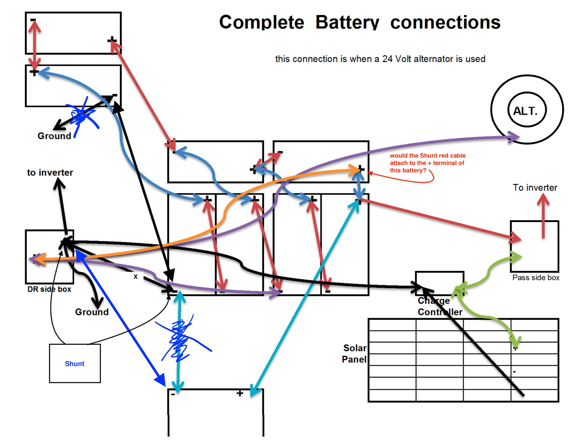
Yes, that is correct. The battery equaliser, is this a balancer type device connected to all 4 batteries in series or a simple charger that boosts to a higher voltage. If it is the first type then leave it connected to the battery negative, if it is the second type connect it to the shunt so any charge it adds is counted.
I am fairly certain the battery equalizer is just for balancing the charge across the banks and is not doing any charging.. but will confirm with the installer.
and just want to confirm the connection for the shunt red cable is correct where I have indicated on the + terminal in the upper right?
thanks again for your guidance
Yes, your red positive cable is correct, I had focused on getting the negative cables right for the SOC measurement and forgot the positive one.
thanks!