I’ve just changed from one multiplus II 48/5000VA (one phase) and PV in AC in to a couple of multiplus II 48/5000VA in parallel setup with the PV in AC out. Also, I’ve a Carlo Gavazzi for the PV inverters (two Huawei 5KTL) and another Carlo Gavazzi for the grid consumption. ESS is properly configured in both multiplus with the PV in AC out.
The problem is that the system is not following the grid setpoint (set to 0W) when the battery is being charged. When it is charging the battery by consuming PV production there is a residual consumption from the grid, around 100W. When it is not charging (for example, when there is not enough PV production or it is dark) the grid setpoint is followed and there is no consumption from the grid. In the ESS configuration “grid metering” (inside Cerbo GX ESS section) I have tried both external meter (carlo gavazzi) and inverter, resulting the same behavior.
Do you guys know what could be happening here? I think this is a software-related issue, but I don’t know what else look or change.
No, I could not fix the underlaying issue. What I did to overcome this issue was changing the Grid Setpoint dynamically. If the battery is charging over 300W, the grid setpoint is set to -200W and that ensures there is no consumption from the Grid. This is not a robust nor a good solution but I didn’t get a response nor an explanation anywhere, so I had no choice. In case you want to do the same, in my case it is just a script that has real-time metrics of the installation and modifies the Grid Setpoint register through Modbus TCP. If you find a solution please let me know …
I’m very disappointed with Victron. I bought a parallel unit, spending even more, because I thought I’d stick with Victron because of its reputation, but in reality the system is crap and old. I’d have been better off with a 6kW DEYE inverter.
It looks like technology from the 2000s.
There are some important considerations when paralleling systems that can affect the behaviour.
First, 2 systems are less efficient than one so any variances in setpoints can be amplified.
If the age of the systems are different, this will affect balance and can make setpoint issues appear. The rule of thumb is the newer unit should be master
Wiring is crucial - too short or too thick (ie low resistance AC connections) can be problematic as well.
You need to use clamp meters, or my node red balance flow, to check what each system is doing independently under different loads.
If there are variations, change your wiring to compensate.
Ultimately different age systems will rarely balance properly, and will wear differently.
There is a science and art to parallel systems. Where not absolutely necessary, I will stick to one and rather sell the older inverter instead of parallel with a younger unit.
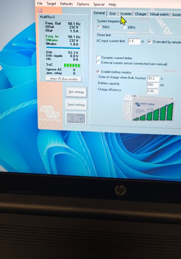
Had I known all this, I would have done it this way. I’d like to take this opportunity to ask: This evening I discovered something that I find strange. When I opened the VEConfigure page in the VE.Bus System Configurator software, in the parameters screen on the left, I see ACout at 0A on the slave device, but when I measure with a current clamp, it’s actually 2A; however, I only see it on the master device. Is this correct in a parallel configuration? Can someone check your parallel configuration? Otherwise, I’ll have to reset everything and reverse the master/slave connections to verify.
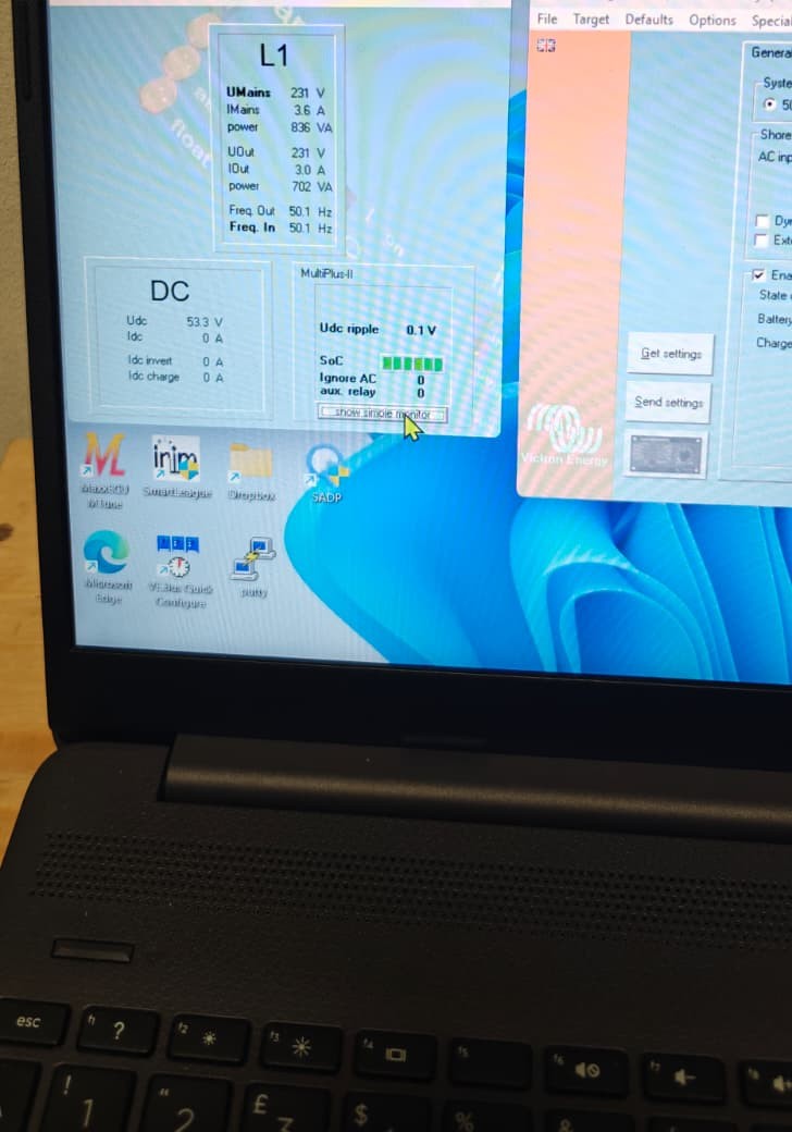
When I open “show VE.Bus monitor,” on both devices, I see realistic AC in and AC out values.
Hi Nick,
I’ve already done that. I also tried installing the previous firmware, but with the same result, so I installed the latest firmware with ve flash and reconfigured everything, one by one. I checked the configuration, and it’s correct for both.
What do you think about the lack of amps displayed on the ACOUT of my slave unit? And about the fact that the vebus sees the correct load?
Thanks Nick, I swapped master/slave, the amperage display on AC out remained 0A on the slave device, which appeared on the master device that was previously not working, so this is correct and my device is not defective. Unfortunately, I’ve never used Node Red, I tried it now, I activated it, loaded your flow but I don’t know how to do it, I think I need to activate a dashboard but I don’t know how.
I’ve swapped the slave and master, being now the master the newest unit. I found out also that the AC IN and AC OUT neutral wires were not the same section as the AC IN and AC OUT phase wires (phase are 6mm2, while the neutral were 4 mm2). I’ve replaced those neutral wires so both phase and neutral wires are now the same section (6mm2). Unfortunately, after doing these changes the behavior is still the same.
I was able to install your flow, @nickdb (congrats btw, it works and looks great!), and found out some imbalance but I am not sure if my conclusions out of that imbalance is correct.
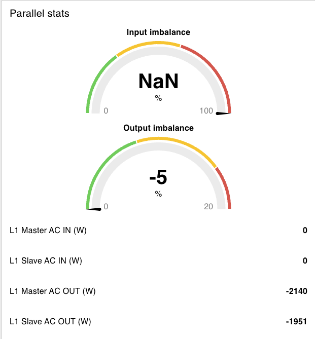
This is how it looks when the system is charging and grid setpoint is set to 0:
There’s a bit of imbalance in the AC OUT lines, but the Slave, which is the unit that receives more energy from the inverters, is also the one that consumes more from the grid…
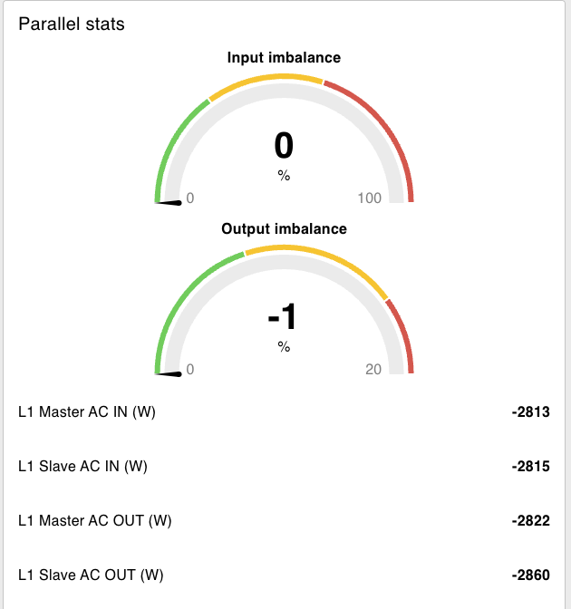
Additionally, if the system is disconnected from the grid, the imbalance looks like this:
After seeing this, I believe there might be an issue in the AC OUT wires (maybe a difference of 1 or 2 cms between Slave and Master wires could cause this?)
An output imbalance of 7% or less is perfectly fine. It will never be perfect. You could probably improve it a little by making the wiring a little more asymmetrical to compensate but I wouldn’t stress about a small variance like that.