I am familiar with Victron equipment and active on this forum.
I am about to add a Multiplus 12/3000/120 (120v) (not multiplus II) to my RV to which I have previously fitted Cerbo GX, IP22, Smart Shunt, Battery Monitor, Orion XS and MPPT.
As per most set-ups, my system is bespoke and I have certain individual requirements and I want particular interface abilities but in order to design them I need to fully understand how the Multiplus behaves.
I have consulted the manual prior to purchase and believe the manual Manual-MultiPlus-3k-120V-firmware-xxxx4xx-EN to be the most up to date for the 120v 12/3000/120 inverter.
I am using a 120v unit because my RV is American thus most equipment is 120v
My questions.
-
The manual for the Multiplus states “3.2 Remote control
Remote control is possible with a 3-way switch or with a Multi Control panel.” Three way switch to me means position A,B or C or more usually on - off - on. There is no example wiring for the remote switch but there is a written description in App A that suggests that there are only two states, those being On (short left pin of connector H to middle pin) or Charge only (short right pin of connector H to middle pin) . Can I select “Off” by having none of the pins connected? (I already understand that the switch on the unit has to be in the “on” position for the remote switch to work. If not then surely the manual should state 3 pin switch rather than 3 way switch? I’ve searched the forum history and general internet and can’t find an answer although one unanswered query suggests that the Multiplus cycles on - off if none of the pins on connector H are connected? -
With the main switch in the “off position” is the AC input switched through? Or does the switch have to be in the “on” or “Charge only” position for the AC to be switched through?
-
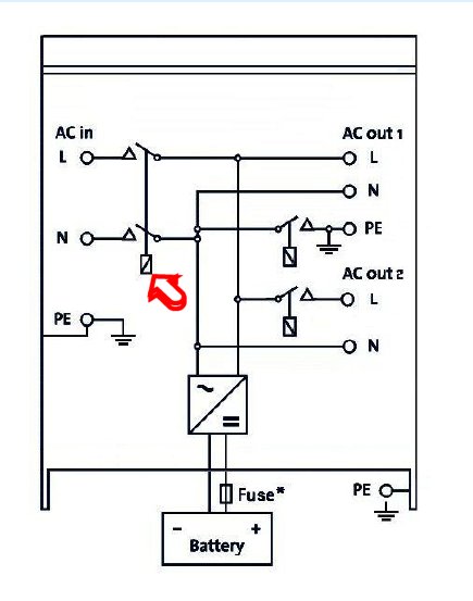
In the manual none of the relays are named. In appendix B (see attached). The relay I have arrowed is obviously the relay that permits AC to be switched through. How is this relay controlled? Is this the “Primary Relay” that is referred to in the “Assistants” when selecting a relay to control (see question 4).
-
VE Configure. I have downloaded VE Configure so that I can familiarise myself with it, especially the “Assistants” as I will need this for my bespoke interface that I mentioned at the beginning of the post. I was expecting to find a “Assistant” that would allow control of one of the controllable relays when the Inverter “On” or rather ready to invert upon the loss of AC input, but I cannot see anything in the list of conditions that fits the bill? On the list of conditions, there is a note that states the if no conditions are set on this or the next page then the relay will always be set. Please define always, I’m not being cute. Is it when DC is available thus truly always or whilst ever the system is on. If it’s the later then it would meet my needs.
-
Final question - In order to enable “Assistants” one has to disable the “Virtual Switch”. Does this mean that I would lose the ability to control ON/CHARGE ONLY/ INVERT ONLY or OFF from my Cerbo GX or is it just control of those items listed on the Virtual Switch page of CE Configure
Many many thanks in advance
Les