In this Victron application note, it is suggested to interconnect the Multiplus II and SolarEdge direct using the Multiplus K1 to put the SolarEdge into Alternative Power Source (APS).
I think it was true before. However, now Multiplus II does not have a real relay but it has an open collector transistor on a 12V power supply. The SolarEdge communication board runs at 5V and moves into APS when on its L1 input it has 5V.
I did not test it but I can guess that if we inject 12V on a board expecting 5V, then one of the other inverters will burn. At the same time, a standard relay would also promote galvanic isolation that, in this case, it does not have anymore.
Question: how can we let Victron knows about it so they can fix this application note if necessary?
I am facing the same question.
And further I am not sure how to configure the aux relay in VEconfig correctly.
Help on these topics would be appreciated.
I have used a optocoupler but I did not test it yet. I have used the open collector relay K1 on Multiplus so to signal, as fast as I could, that the inverter should move into APS.
However, if you put some thought on it, it just doesn’t make sense. The SolarEdge always be on the AC OUT and, if so, we could just enable APS with a jumper and never let the SolarEdge be independent. If the Multiplus goes down, the SOlarEdge will always go down.
And yes, I would love to get more support from the community but I guess this is quite specific and few people has crossed this problem so far.
I had the same issue and the application note is only valid for older Multiplus where K1 was a relay, but e.g. with the Multiplus2 you cannot use K1 so easily due to the OpenCollector contact implementation. I asked Solaredge for the electrical spec of the PRI but they forwarded me the sales team…
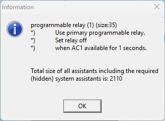
BUT meanwhile I found out you can use the so called “Alarm contact” which is actual the mentioned programmable relais and also state as AUX RELAY on the MP2.
The one thing I am not sure about yet is the timing for the OnGrid trigger, if I have to increase the timing to around 60s what the MP2 almost takes to switch on the internal AC relays again. I guess it is directly bounded to my grid code in germany.
The SolarEdge inverter already switches back to Grid Code config although the MP2 has not released to grid to AC out yet.
I aggree Victron should update the application note according that as if they mention that as examples => you see people are goint to go in a wrong direction.
Tested the mains faillure and the K1 switched on after a delay of 10 sec. (As set per relais assistant)
When the PV is generating more than 2 kW power and the Battery’s are 95% i will test the entire mains fail/emergency/mains restored procedure and report here asap.
The SolarEdge APS mode, that we use to force using a relay, is only necessary if the grid goes down and your batteries are full charged. In this case, the Multiplus would have no place to put the generated solar power so it will increase its micro-grid frequency to force the SolarEdge reduce its production. The SolarEdge will only modulate its production based on frequency case it is in APS mode.
This said, Venus OS 3.6 and above, when integrated with SolarEdge via modbus SunSpec, will be able to reduce de SolarEdge production using SunSpec. Take a look in this release notes. Once there, do a search for “PV Inverter limiter support“.
As i understood reading, when the Suncpec function is configured, TSO/DSO will always be in charge of your private PV inverter power/reactive power control setpoints or do i read these control strategies wrong?
Than found this 2025 topic, it is still not clear to me, is this a function control in the GX, so no external signal from TSO/DSO influences the control setpoints?
Sorry phaseshifter, I may be misunderstanding your question.
If by TSO you mean Transmission System Operator and by DSO you mean Distribution System Operator, then I do not think that is the key point here.
The important issue is what happens when the SolarEdge inverter is operating in an islanded micro-grid, after the grid has failed. In that situation, if PV production is higher than the loads, and the MultiPlus batteries are already full, the system must be able to curtail the SolarEdge output to avoid overproduction.
One way to do that is to configure the SolarEdge for APS mode and configure the MultiPlus to use frequency shifting, so the SolarEdge reduces power as frequency rises. Victron’s own SolarEdge integration notes describe this approach. In addition, SolarEdge also supports SunSpec/Modbus, which can be used for inverter monitoring and power control in supported Victron GX integrations.
So, in my view, the real question is not TSO vs DSO, but rather how SolarEdge power is controlled during islanded operation and when the batteries are full.