I have a system that consists of two Multiplus 12/3000/120-50 units set up in a 120/240 split phase arrangement.
The multis are fed from a variety of ‘grid’ power sources including a 120/240 9kW generator, 120/240 50A ‘shore’ power, or 120V 30A ‘shore’ power fed through a Victron autotransformer to provide 120/240 15A power to the multis.
The system works well with one exception. When I connect to generator power, the system takes a short period of time (perhaps 5-10 seconds) to recognize the AC mains power and switch over from inverter. The same happens when I connect to various 120/240V 50A shore connections. However, when I connect to a particular 120V 30A shore connection, which is fed through an autotransformer to provide 120/240 split phase to the MPs, the system typically takes much longer to recognize the mains power in, and often refuses to accept the mains power, staying in inverter mode. This rejection occurs perhaps 10% of the time. If I disconnect and re-try, I can always get it to accept the mains power in, eventually.
A bit more detail on the 120/30A connection: I have only ever tried to connect it to one particular 30A supply, so I’m not sure if the problem is tied to the 120/30A/autotransformer, or perhaps this particular 30A supply. The voltage on this 120/30A supply is somewhat low, typically around 114V, although sometimes as low as 109V and sometimes as high as 117V. Whether the 30A supply is high in that range or low in that range does not seem to affect how it accepts/rejects the mains power in. As mentioned, it is fed through an autotransformer. This autotransformer boosts the output of L2 by about 5% relative to the input voltage, so typical voltage into the L1 MP is 114V, and typical voltage into the L2 MP is about 120V. As I understand it, this 5% is within the normal manufacturing tolerances of a Victron autotransformer.
A few more details: ‘Accept wide input frequency range’ is left on by default (although connections are all 60Hz±1Hz); AC low and high voltage disconnect levels are default, which are well outside the voltages that are coming in (I believe default settings are 90V and 135V, respectively).
My question is why does the system take longer to accept the 120/240 from the autotransformer, and more importantly, why does it refuse to accept it on occasion? What characteristics are the MPs checking before connecting to the mains? What are the thresholds of these characteristics?
Another point that may or may not be interesting…I can seemingly force the MPs to make a decision on whether or not they accept the grid connection by switching the digital multi control from ‘ON’ to ‘Charger Only’. I don’t like to do this because I lose AC power while the MPs decide whether or not to accept the grid connection (I would estimate 3 seconds), causing certain devices to lose power and reboot etc. However, it does not seem to change the likelihood of them actually accepting the grid connection. I have looked for errors or explanations on the Cerbo for the cause of rejection and do not see anything.
As mentioned above, I know the voltages and frequency are within the limits specified in the MP configuration, I’m just not sure what else they are looking at. I plan to hook up an oscilloscope to check the waveform but this is ‘city’ grid power, so I’m not expecting anything funky. I wonder if there is a tolerance for L1 voltage vs. L2 voltage but cannot find that specified anywhere.
I should also mention it doesn’t seem to matter whether or not there is an AC load on the system when connecting. I have tried to connect to the grid with things powered on as well as connect with zero AC loads on the system and it doesn’t make a difference. Also, I have PowerAssist and Dynamic current limiter turned ON, although I don’t see how this is pertinent.
This is two different states. In charger only it does not have to synchronize to the source wave form only pass it through.
As a source appears on the input, the system will try match the incoming, then power assist as it connects. If it is failing to do it, this can be for a few reasons, one can be that it cannot draw the amps from the battery needed to prepare to do so. (It is the increased hum you hear that happens before the relay click.) either an unwell battery or high resistance connection to the battery?
The other could be a high resistance connection to the grid side, which can also cause a few funny behaviours with synchronization.
You could always try a firmware update (and re program) after physical checks.
Hi thanks for the reply. Good point that when in charge only it doesn’t need to sync in this state, only accept.
You mention that it can fail to connect for a few reasons. Then you two specific potential reasons:
-cannot draw the amps from the battery
-high resistance connection to the grid side
It certainly is not the first reason. I have confirmed that the behavior does not change even when there is no load on the AC system. I have also confirmed that there is low voltage drop even when both MPs are drawing hundreds of amps from the batteries while inverting. It is a new installation with new 4/0 cabling and new, appropriate terminations, and a new LFP bank. There is never a problem running the system when in inverter mode, nor when connecting to ‘grid’ power from the generator or 120/240V 50A sources (and the batteries/DC system are a constant across these scenarios).
The second option is an interesting thought–there could be a high resistance connection somewhere on the grid side, for sure. However, if this were the cause, I would expect the rejection to be much more likely when there is a load on the AC system. Again, it is just as likely to reject the grid connection even when there is zero load on the AC system. Additionally, the relays that connect the grid to the AC system are quite loud and therefore easy to hear actuate. The MPs are not switching over, seeing strange behavior, and then disconnecting. They are just refusing to connect, so it is not as if the AC voltage is being pulled down by AC loading before the rejection.
Firmware is up to date and I have reprogrammed the MPs several times to tweak various settings and this behavior is not affected one way or the other.
I appreciate you helping me brainstorm possible causes! It would be great to see an entire list of parameters the MPs look for when deciding whether or not they will accept grid input. I suspect it is related to the split phase arrangement of the MPs combined with something ‘unusual’ about the 30A 120V–>15A 120/240 grid connection, although I am not sure ‘what’.
It is interesting how it is not even attempting to connect and you don’t have any conditions on connect to ac active. I don’t have experience with split phase exactly, but on multi phase systems and parallel I do. The only time i have seen v a system do nothing when grid appeared was when it was the wrong way around oahse wise.
I think I will try to ask the question a different way:
When two MP’s are set up in a split phase arrangement and connected to a ‘grid’ supply, it goes through a process of qualifying the grid supply before accepting it and closing the Transfer switch. What are the details of this qualification process? What does it look at and what are the limits?
I am sure it looks at the voltage of L1 and ensures it is within the range specified in the programming (AC high connect, AC low connect), as well as the frequency, ensuring it is within the range specified in the programming (Accept wide input frequency range is checked). I am sure it does this for L2 as well. I have confirmed that both L1 and L2 meet these requirements and yet it still occasionally rejects grid connection. Is anyone familiar with the entire list of things it checks before accepting the grid power? Is this documented anywhere?
Not tripping ELCI, so doubt there is a current on ground. That said, is this detailed somewhere in the documentation?
Great tip on ve config…never knew it would highlight the reason(s) the AC input is rejected! I will try this ASAP! However, based on the screen shots in the link, it is giving me the impression it will only highlight the reason if it is frequency or Vmains based on the color scheme(?). Regardless, it seems like a great place to start…thanks!
As an option uncheck this as the idea of wide frequency and then a ups function are a bit contradictory… it is either tolerant (wide frequency and a bit iffy) or not (ups).
More great info, thanks. I guess I never had a full understanding of the ramifications of selecting UPS function. Victron says “UPS Function determines whether the Multi should be critical of the distortion in the supply waveform.“ I would prefer that they put numbers to this, like THD ≥x% will prevent connection, and it seems obvious that when connection is rejected for waveform distortion (or any other reason), that reason should be displayed somewhere. Regardless, I have a new appreciation for what it is doing. I have a strong suspicion this my be my problem. My plan is to connect up VE Config and see if that gives me any clues while connecting to the grid supply. I will also take a look at the waveform of the grid supply with a scope. Finally, I will experiment with checking/unchecking the UPS function. I suspect that after these three steps it will come into focus. Thanks, you have been really helpful.
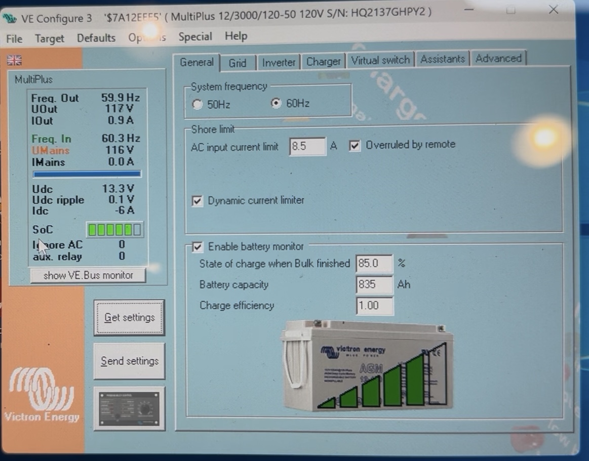
So I wanted to report back w/what I found in case anyone ever finds this thread through a search (and I like happy endings). I was able to determine the root cause of the problem, and it surprised me! LX’s tip on using VE Configure to monitor things while it was attempting to connect was key. Below is a screenshot of what I would see after hooking up to shore and having it reject the grid connection:
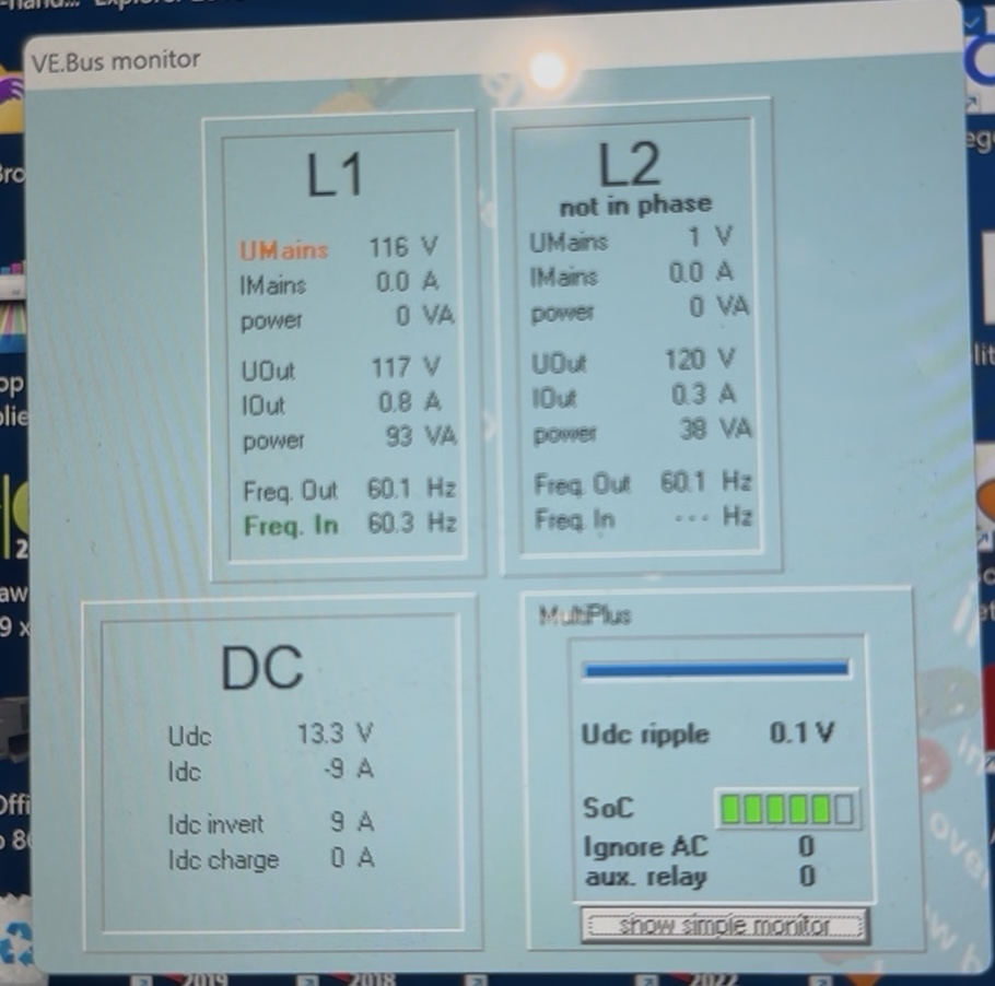
Note the ‘VMains’ is within range at 116V but still red. That annoyed me, as I felt it should be more descriptive. Then I clicked on the ‘show VE.Bus monitor’ button, and a second screen showing both MP’s at the same time appeared:
Now it became more obvious, it was listing 1V as the input to the L2 MP. I knew this wasn’t right as I have a voltmeter at the AC panel before the MPs (the panel is used to select the source–Shore 1, Shore 2, Generator), and the voltmeter is showing good voltage on both L1 and L2. Now I’m thinking something it glitchy with the L2 MP, but grab my meter to confirm there is good voltage at the L2 MP. To my shock, it was in fact around zero volts! The selector panel uses three triple-pole breakers with a mechanical lockout to select the chosen source. Turns out the L2 breaker on the 120/240 15A source selector is intermittent! The voltmeter is on the input side of the of the breaker, which is why it was showing good voltage. Problem solved. I Victron should have an error message show up in a log or on the Cerbo, or somewhere other than having to connect a laptop and going into VE.Bus Sys Configurator then VE Configure to see this info, but I’m glad to know how to access it. If someone knows of a simpler way to get to this information using Cerbo or VRM, I’d like to learn that.
To anyone having trouble understanding why your MP(s) won’t connect to the grid, start by monitoring the above screens in VE Configure. Thx to TX!
One more note about the VE.Bus monitor screen in the previous post. Note that in the L2 box, it says ‘not in phase’. I found this interesting. The 1V it is seeing is just noise, so not surprising it was ‘not in phase’ with L1. But I experimented a bit with this as I was always curious about the requirements of the phase relationship between L1 and L2 when arranged in a ‘Dual phase 180’ (split phase arrangement) with one of the ‘L2 floating’ options checked. I could not find any hard evidence on what the requirements were between L1 and L2 with this option checked in Victron documentation, but did find some reference on the old Victron community site that it was 180°±60°. I decided to test this out, to an extent, by feeding the L2 MP with the same phase as the L1 MP. Perhaps not surprisingly, the system rejected the grid input when L1 and L2 were the same phase.
Perhaps surprisingly, the VE.Bus monitor read ‘not in phase’ as shown above, even though L1 & L2 were perfectly in-phase. When fed with L1 & L2 180° out of phase, the ‘not in phase’ message disappears, and the grid connection is accepted.
Bottom line is that the ‘not in phase’ message seems to actually mean ‘not in expected phase arrangement’, not actually ‘not in phase’. Perhaps this will help someone in the future.