I’m running a MultiPlus-II 5000/70-50 inverter with a 1000Ah 48V battery bank — more than adequate for my off-grid setup. Despite low inverter load, full battery capacity, and peak solar input (up to 4000W), I’m consistently seeing momentary light dimming whenever one of my house water pumps (1000W) starts. Simultaneously, one of my desktop computers restarts, which I suspect is due to the PSU’s limited hold-up time.
While I acknowledge the PSU may need upgrading, I’m curious whether this behavior could be mitigated through inverter configuration. Specifically, are there any settings or firmware parameters that could reduce or eliminate these transient voltage dips?
Notably, my previous inverter — a Selectronic SE43 — never exhibited this issue. It seemed to offer:
Robust surge handling (possibly due to oversized output capacitors)
Lower output impedance (better absorption of inrush currents)
Tighter voltage regulation during transient events
The MultiPlus-II has otherwise performed well, but its response to inductive load startup is concerning. Are there adjustments available for:
Output impedance characteristics
Firmware settings such as UPS mode, Dynamic Current Limit, or others relevant to surge handling?
Any insights or recommendations would be appreciated — especially if others have tuned their systems to handle similar scenarios.
Wiring gauge and set up play a huge part on surge load handling. For our systen that have big induction load we use much heavier gauge dc cables then the min recommendation in the manuals.
No there is not.
So yes echoing @ChiefSolar we would like to know what has been done in your set up.
Run a higher voltage (240v) on the output if you are inverting is also a work around if your set up is good and there are no other issues. (Grid connection this makes no difference)
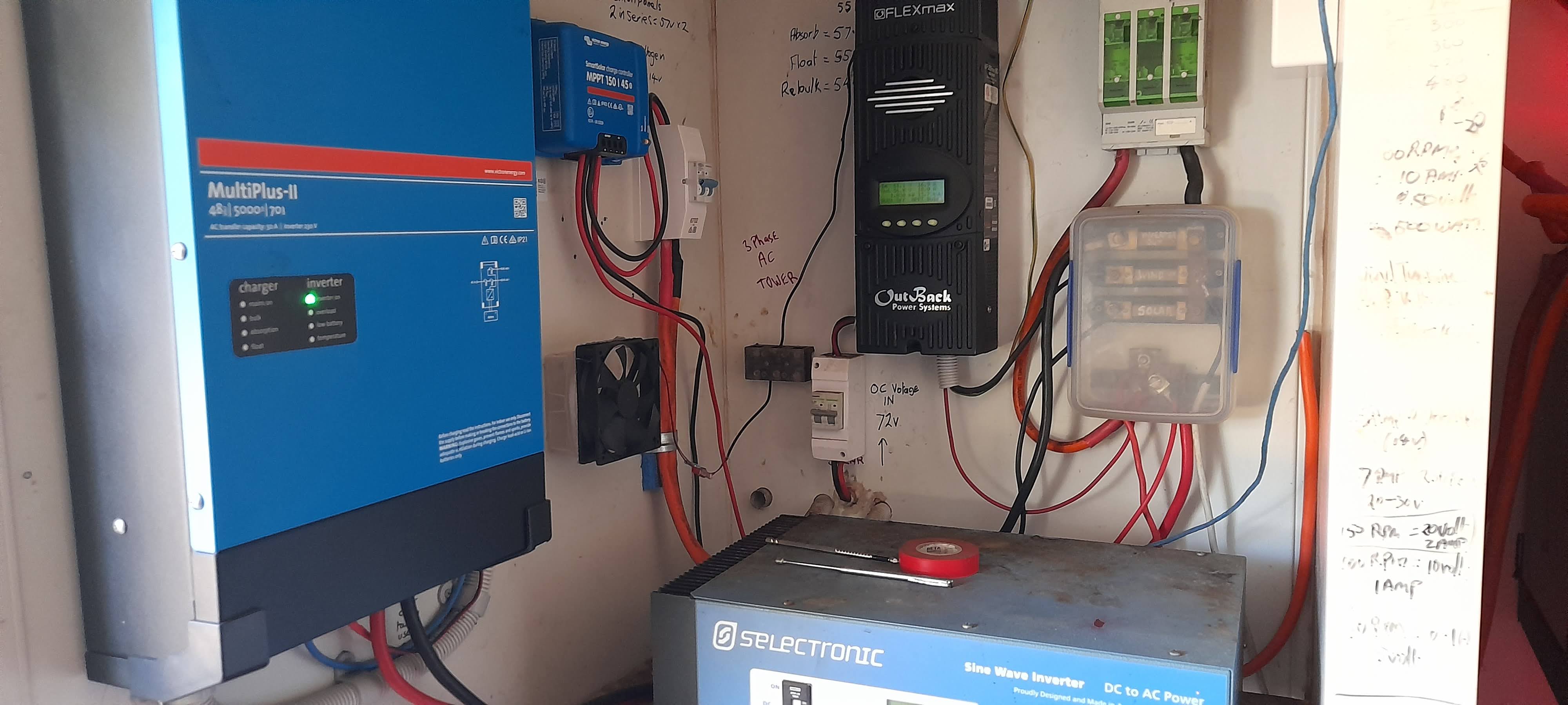
Thanks for the replies. I’ve now attached both the schematic and a photo of the system as requested.
To clarify:
I’ve been operating off-grid for 18 years using a Selectronic SE43 inverter, with the same cabling and load profile now connected to the Victron MultiPlus-II.
The SE43 ran flawlessly — no flicker, no reboots — until I replaced it in 2023 as a precaution due to age.
Since installing the Victron, I’ve experienced momentary voltage sags and PC resets when small inductive loads (e.g., a 750W house water pump) start.
Let’s be clear:
Battery cabling is 2/0 AWG (9.3mm diameter), 2 meters long
Battery bank is 1000Ah @ 48V
Voltage at inverter is consistently 50V+, dipping only slightly to ~48.5V at night
Zero measurable voltage drop between battery bank and inverter
The pump is in good condition and not exhibiting excessive inrush behavior
So yes — logic dictates the only change in the system is the inverter. Suggesting I “increase output voltage to 240V” is a superficial workaround, not a solution. If that were sufficient, the SE43 wouldn’t have outperformed the Victron in surge handling, voltage stability, and transient response.
I’m asking whether the MultiPlus-II offers any advanced configuration options — via VE.Bus or otherwise — to improve its behavior under inductive load startup. Specifically:
Can UPS mode or dynamic current limit be tuned to reduce output sag?
Is there any internal impedance or firmware-level adjustment available?
Can the inverter be configured to match the robustness of legacy units like the SE43?
I’m not looking for generic advice — I’m looking for engineering-level insight into how this inverter handles transients, and whether it can be tuned to do better.
Thanks in advance to anyone who can speak to that.
The multplus 2 has a large inductor in it. It will behave totally differently to your previous one as it is a different design and topology. A closer equivalent to it would have been Multi RS.
Increase the gauge of wire or double the run between inverter so 2x 70mm² cable (or 2x50mm²). This falls into the guidlines in the install manual.
It will speed up rejection and switching time and make the inverter more critical of the sine wave. Described here.
No. And it is influenced by physical installation.
All inductive loads will produce a voltage sag when running off-grid through a low-frequency inverter. What kind of an inverter is the Selectronic?
My 750W nominal water pump even produces a voltage sag when connected to the grid on my setup, fwiw. Water pumps can easily draw 4x their nominal power while starting up, some of them can go up to 8x. Installing a VFR is the best way to address this effect, there are mission-specific VFRs that connect directly to a pressure sensor and also keep the pressure constant.
Voltage sag is worse when DC-bus cable used is smaller than the required, or when the battery bank is smaller than required (or its cells are old). Please provide more info on the battery bank used.
They are already using 2/0 AWG cable, which is equivalent to 70mm². Although it does not look like that thick, judging from the photos shared.
Agreed. It may be an artifact of the camera? Not sure.
What is being described sounds like insufficient dc so maybe your comment and @ChiefSolar’s is on the right track it is related to the battery.
Could not find anything conclusive online about them. They have a similar weight to the MP25kVa. But if it is an older inverter it is likely a different type to the torroid so will have vastly different behvaour.
And yes voltage sag is normal even on the Multi RS it can be seen on an O scope.
Thanks all for the input. I’ve reviewed the suggestions and would like to offer a consolidated response that hopefully elevates the conversation beyond the usual suspects of cable gauge and battery chemistry.
To clarify:
I’ve been operating off-grid for 18 years using a Selectronic SE43 inverter — same cabling, same pumps, same size battery bank (replaced).
The SE43 never exhibited flicker, voltage instability, or PC resets under inductive load.
In 2023, I replaced it with a Victron MultiPlus-II 5000/70-50 as a precaution due to age. That’s the only change in the system.
Battery cabling is 2/0 AWG (≈70mm²), 2m long, with zero voltage drop.
Battery bank is 1000Ah @ 48V, consistently delivering 50V+ at the inverter.
The pump in question is 750W and in good condition — not a high inrush unit.
So respectfully, suggestions to double the cable size or question battery chemistry are not relevant under these conditions. We’re talking about a 300W background load and a modest pump — well within the inverter’s continuous rating. If the system were under stress, I’d expect voltage sag across the DC bus or measurable drop at the inverter terminals. There is none.
I’m not chasing ghosts here — what I’m observing is more nuanced:
A momentary flicker on a 12V LED circuit powered by a regulated AC-DC supply
A PC reset that correlates with pump startup
No evidence of sustained voltage sag, but possibly a transient waveform distortion or switching artifact
This doesn’t behave like a classic voltage dip. It feels more like a brief modulation anomaly — the kind you’d expect from internal switching, phase shift, or waveform recalibration under load step conditions. The SE43 may have masked this with heavier output filtering or lower impedance. The MultiPlus-II, while modern and modular, may expose more of the raw transient behavior.
I understand from your replies that there’s no firmware-level adjustment available to tune the inverter’s transient response — which is disappointing, especially given how robust and forgiving the SE43 proved to be in real-world conditions. If this behavior is simply a design limitation of the MultiPlus-II’s topology, then I’ll accept the flicker as the new normal.
Still, I’d appreciate hearing from anyone familiar with the inverter’s internal response mechanisms — beyond what’s covered in the install manual — to confirm whether this behavior is expected, or if it might indicate something atypical in my unit.
Thanks again — and I hope this prompts a deeper look at how Victron gear handles real-world transients, not just textbook loads.
Well. You know what. I bought a cabin in Norway (offgrid) with 4 lead acid batteries.They looked clean and nice. Well maintained. Even a small booklet with when the previous owner checked them. Anyway. My wife and kids noticed the flikkering and I went looking for the cause. Guess what. One of the (almost) two year old batteries had issues with the load.
I first replaced them with one 48V LFP battery and the problem was gone. The battery was still under warranty and later replaced. Problem solved. We since replaced everything (for 3 fase EV charging) but that’s really off topic.
Let me add that we ran everything on one single Victron Multiplus II 48/5000. From induction cooktop, airfryer, instand pot, water kettle and our the well pump.
Thanks for sharing your experience — I appreciate the anecdote. I’m glad your battery replacement resolved the issue in your case, but I’m looking for insight into the inverter’s behavior under real-world inductive load conditions — not just obvious battery faults.
My situation is not a battery fault. I’m running two parallel banks of 24 × 2V AGM cells (500Ah each), totaling 1000Ah @ 48V. That’s a very different architecture from a series string of four 12V batteries, where a single faulty unit can cause a 25% drop in both voltage and capacity under load. In my case, even if one or two cells were weak, the impact would be minimal unless the state of charge was low — and the flicker I’m observing occurs even at full SOC with 4kW of solar available. I’ve previously mentioned that the voltage at the inverter is consistently 50V+, and there’s zero measurable drop across the DC cabling.
Can we just take it that all else is well with my system and focus on what might be possible on the inverter side? If the answer is “nothing,” that’s fine — I can troubleshoot other components myself. I simply want to be confident that the inverter isn’t exhibiting a fault before I start fixing things that aren’t broken.
I only used my cabins setup as an example, because your drawing shows four batteries in series.
So. You basically have a 500Ah battery setup. Effectively. You did not share the requested graph showing the voltage / amperage. There’s no close ups from the battery, wiring and cable lugs. You ask us to focus on the Victron inverter, trust the setup, without showing what we need.
And about real world inductive loads. At home I also have a Victron setup running. There I have a ton of inductive loads. In the cabin less, but some heavy pullers. So with almost 900 setups. Decades of experience. I’ve seen a couple of these problems. Guess what. They all came out as setup errors.
Yours might be different. But I’m not ruling out anything… just because your setup worked with a different inverter.
Let me tell you something else. I had a customer last week who destroyed a Victron PCB by over torquing the battery cables. Two others crimped their battery cables themselves. Well. We ended up replacing them. Problem solved. In other words. There could be something wrong.
Yes. I myself have made errors as well. Silly stupid errors usually late in the evening or under a lot of stress. In short. You and I may actually not see the actual problem.
And that’s fine. But please don’t ask us to look to the other side. If you want help. Provide what was asked.
Have a nice day. Note that most of us here are doing this in their spare time. Free of charge
Mate… I appreciate you’re doing this in your spare time for free, so let’s save both of us some time. It would help if you weren’t defensive, anecdotal, and ultimately evasive — sidestepping the core of my inquiry and leaning on personal experience and installation volume, when none of the examples you’ve offered are remotely relevant to my setup.
You originally asked for a wire diagram — which I provided. I didn’t expect you to assume the battery symbol represented my actual bank. (I can draw 48 batteries if that helps.)
And no, it’s not 500Ah. It’s two banks of 500Ah in parallel — 1000Ah total.
I’ve already confirmed:
Cable size is adequate
There’s zero voltage drop between batteries and inverter
The only thing I didn’t provide was a voltage/amp graph — which is overkill given the confirmed stability and capacity of the system.
Rather than revisiting your anecdotes, it would be more useful to acknowledge what’s patently obvious: if I can draw a continuous 4000W load without cables heating up or battery voltage collapsing, then the DC side is not the issue.
I’m fully aware we all make mistakes, and I’m happy to send photos of the battery banks, wiring, and lugs — but frankly, that would be a wild goose chase.
So we can keep trading stories, or you can simply state whether — all other things being equal — there’s any idiosyncratic feature of the Victron MultiPlus-II 5000/70-50 inverter that might result in transient output instability, waveform distortion, phase shift, or modulation anomalies during inductive load startup. That’s the level of insight I’m after — not whether my crimping tool was sharp enough.
It is rather difficult to pin point the problem without data from a power analyzer. Which is what I would use in a case like this. So yeah. Sure. I do have a hunch, but I was reluctant to ventilate that… due to the lack of factual evidence that it is the problem. I could be right, but I could also be wrong.
Now. What I think. We all do I guess. Is that you seem to have some sort of inrush that is crippling the output of the Multiplus. Enough for you to notice it. The Multiplus II is a different kind of inverter, than your previous inverter (probably with a small capacitor bank in it) and the Victron Multiplus II seems incapable of handling the load. Ergo. You probably need a second inverter or a bigger one. That is what we usually do…after figuring out what exactly the problem is. We did however also install a couple of capacitor banks earlier this year. That fixed the power quality. Different, but fun.
Sorry for editing. I needed to help lift something here
It sounds like your voltage sag might be due to inrush current from the inductive load—have you checked if the DC voltage drops sharply at startup, or tried adding a soft-start device to reduce the surge?
That’s what he said. And a soft starter could be a good idea. If you know what the problem is. And not too many are required.
I thought about it. Why we don’t see this sort of issues here. It’s probably because we happen to have lots of setups with AC coupled solar. Inverters on either AC in and/or AC out.
I read somewhere that you may not measure any voltage drop until a particular load kicks in?
Also, inrush current varies with a specific load. One inductive load might not cause a voltage drop but another inductive load might cause a voltage drop.
I suppose that’s one of the reasons some MM can measure the inrush voltage draw of a given device.
Thanks all — I appreciate the input and the constructive suggestions.
I’ll double-check the inrush characteristics and confirm DC stability under load once more before considering any additions like soft-start devices or inverter expansion. As mentioned earlier, the only significant issue was the PC false restarts, which I suspect will be resolved with the reinstatement of the original PSU.
If the flicker is all that remains, I can live with it — at least it gives me a free notification system for when the pump kicks in.