I have a Lynx BMS NG and two 24V 200Ah NG batteries in my system. The system was professionally installled. The batteries are installed in parrallel, and can be charged by multiple power sources. One possible charging source is a generator. The generator, is connected to a Quattro 24/8000/200. This gives the ability to charge each of the batteries at up to 0.5C (100amps). Victron’s recommended maximum continuous charge current for these batteries is 0.5C. Notwithstanding this ability, the maximum continuous charge current in my system has been reduced to a combined total of 180amps, therefore approximately 90 amps for each battery or 0.45C. This is below Victron’s recommended level.
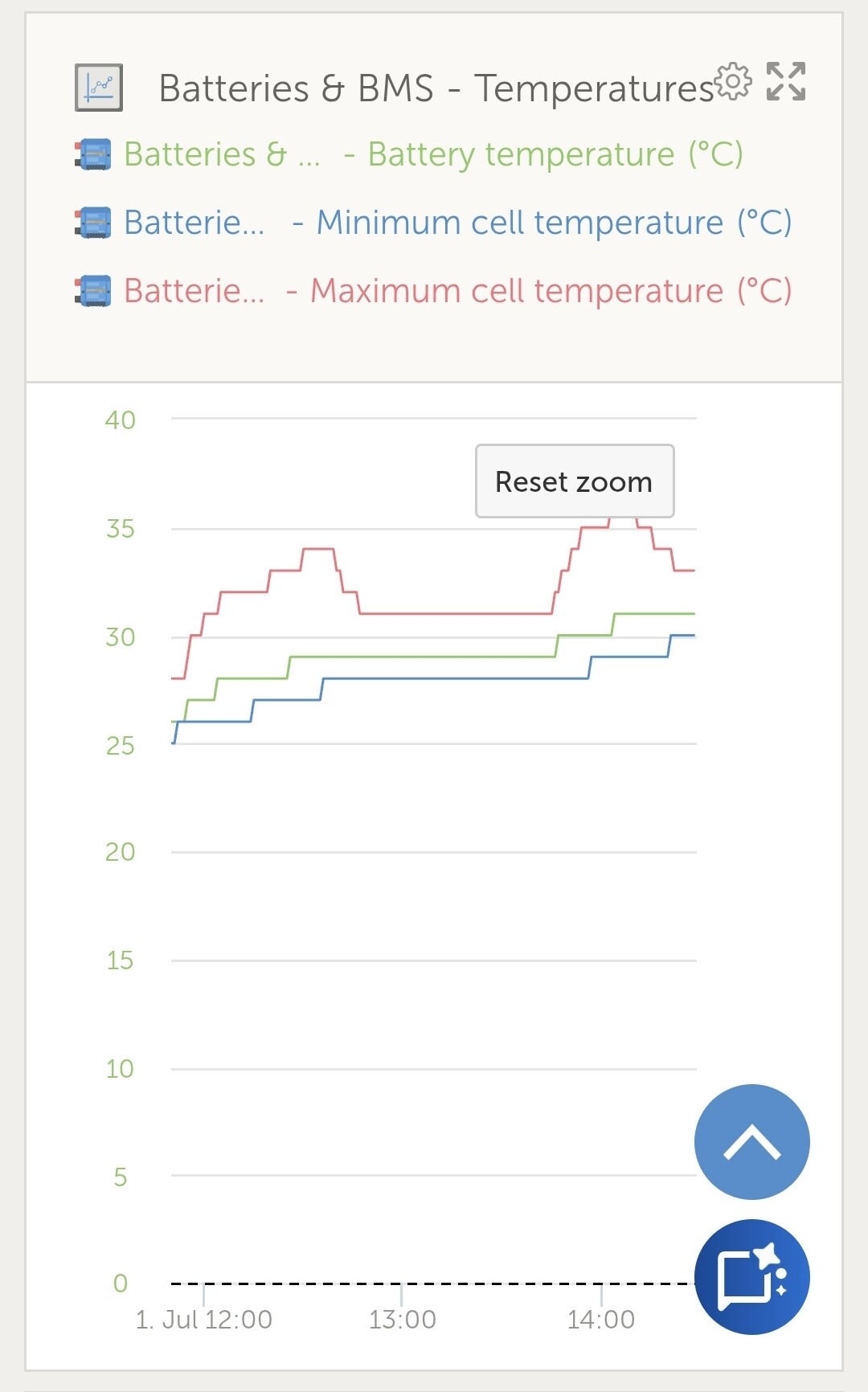
Notwithstanding these settings, we have noticed increasing maximum cell temperatures, recorded by the BMS and a widening spread during charging for the minimum and maximum cell temperature readings. Whilst these temperatures are below the level the system will shut down charging and loads, the rising values and their rate of change seem high, given the batteries are rated at 1.0C however are only being charged at 0.45C, see screenshot.
No guidance appears to be given regarding the expected temperatures that may occur while charging. So my question to the community is: What termperature levels are normal (during charging) and what levels do other users typically see for cell temperatures. Are your results similar to that shown in the attached screenshot?
On a related issue, providing only the minimum and maximum cell temperatures for the entire bank is a bit disappointing and hopefully will be addressed with a firmware update. If more information was provided, then it would assist identifying problematic cells. eg if all cells, in my example were around the same temperature, and only one (being the maximum) is an outlier, then it may mean there is a possible issue or a least closely monitoring needs to continue.
Currently temperature readings only appear to be provided on a battery by battery basis. I’m not sure if this figure is an average for the cells in each battery or just the value for one sensor - i’m thinking it maybe an average. As noted above, there are also minimum and maximum temperature readings provided for the entire bank. In my bank there are only two batteries, which have a total of 16 cells. Given the NG system is designed for upto 50 batteries and therefore a system that could have 400 cells providing only 2 readings for upto 400 cells seems inadequate. More information is required to identify which cell or at least which battery contains the cell with the minimum and maximum readings. Without this information it makes isolating a faulty cell or battery difficult. If anyone in the community can provide more information about gaining more information from the NG batteries, on a cell by cell basis for temperature readings this would be appreciated.
While I can not provide comparative figures because I charge at 0.2C (120A into 600Ah, 2 x 12V 300Ah NG) here is a bit of data.
Charging from 40% SOC starting from 10/11degC min/max climbed to 21/24. Charging from 85% starting from 19/20 climbed to 21/23. Charging from 70% starting at 13/14 climbed to 19/23.
There is a definite trend of widening temperatures during the charge. I have not done many cycles yet to see any worsening. What I have noticed is if I charge off shorepower then the temperatures do not widen as much as charging off my engine alternator as my batteries are in the engine bay. Therefore, I believe that there is some secondary effect in my case. Even when the batteries are full and charging has stopped when underway the temperature remains around 3degC spread. This combination of charging and the installation environment makes it harder to interpret.
Thank you for your information. My batteries are located under a couch, in the main saloon and therefore should not be impacted too much by other enviromental issues. During the charging cycle shown with the data I had the batteries well ventiated with all of the couch cushions off for observational purposes. Typically this would not be the case, so heat from the Quattro, located adjacent to the area with batteries may slightly impact the ambient temperature.
The starting temperature, recorded for the my batteries was therefore effectively ambient temperature and not impacted by other factors. As noted starting at 22C and getting to 36C, in this cycle did not trigger the max temperature ATC or ATD events. I am located in Sydney, Australia and it is currently Autumn - so a bit cooler. Ambient temperatures in summer and further North can be much warmer. If charging results in approximataely a 14C rise, then this maybe become an issue when ambient temperatures are higher.
In regard to the actual results, I am still very much in the dark about whether or not I am seeing an outlier for the maximum cell temperature versus the opposite. More data for all of the cells is needed. Do you have any thoughts on this issue?
My installer will be discussing the temperature issues with the local Victron Distributor. We feel there maybe an issue with the batteries. BTW current recorded by the VRM is for the entire bank, it is not battery by battery. The current supplied to each battery is approximataly 50% each; however it does vary. Initially it was about 90amps for battery 1 and 80amps for battery 2. Towards the end of the charging phase this balance reversed with battery 2 taking more of the lowering current during the tail off phase. This information can only be obtained using a blue tooth connection to the BMS, using a phone or other blue tooth device. I do not beleive it is recorded anywhere. More information, which IMO should be on the VRM and recorded.
OK, the temps rising continuously through the bulk phase, and as soon as the current reduced during absorption the max temp subsided so it definitely looks like a resistive heating effect in there and the speed it fell suggests no thermal inertia like a call would have. Perhaps the one temp probe is out of position and picking up heat from a cell interconnect or terminal rather than the cell. Once charging ceases the min/ max differences is similar to mine after a long charge, 3degC difference on my longest charge with shorepower. When mine stop charging after a long charge they do not show that sharp drop. A look inside by the dealer to check the temperature sensor locations may be all that is required.
In terms of your heating up from 45% to 100% SOC you saw 10degC rise, my largest charge detailed above from 40% to 100% used shorepower not the engine so no secondary effects and rose by 10degC. Therefore your numbers are in line with mine on average which is a good cross check.
I had a similar problem to this, especially the spike at the end of the charge cycle was concerning. It turns out the problem was the heat from the battery cables themselves, which were run on top of the batteries. They were in a bundle sitting on top of the batteries, and the heat from the cables was creating a hot spot for one of the BMS cards in the battery. I made some air under the cables and the problem went away.
It’s also helpful to get out an infrared camera and look at the heat of the cables and connectors, I did find that one of the negative cables was running a bit hotter (likely due to a minor issue with the lug crimp). It wasn’t dangerously hot, but it was enough to transmit some more heat through the negative stud, and into the cell and BMS that is on that side of the battery.
Long story short, check out the environment around the battery when looking for hot spots like this. An infrared camera is very helpful.
Funny you should post this, I developed a loose connection on one battery terminal sometime after this topic but never thought to revisit it afterwards. I got higher maximum cell temperature inconsistent with min call temperature and nominal battery temperature. It went when I tightened it up again. It probably loosened due to vibration from the engine. Here is my plot of min cell, max cell and nominal battery temperatures with the max cell T clearly showing a rapid fall as charge current reduced.
Yeah the delta I’m seeing now is about 4-5 celcius, directionally aligned with yours. This is whilst charging at about 0.38-0.4C (mine is closer to 4-5C, and I think I still have some inconsistent resistance in one of the cables to fix up, but even that level of delta is fine, when the batteries were finishing charging it was approaching a 8-10 celcius delta which was getting concerning).
The concept of having temperature measurements within the battery itself is definitely a new concept for those of us moving from lead-acid batteries. In hindsight looking for localized external heat sources seems obvious. Perhaps something to suggest for the Victron installation guidelines…
I believe, based on a number of test cycles that I have also been able to resolve the issues I experienced with rapidly rising and diverging (maximum and minimum) cell temperatures, observed while charging my Lithium NG batteries. The likely issue appears to the terminal connections. Specifically the torque settings applied to connect the cables/lugs to the battery terminals. Initally all cables/lugs were attached to the terminals as per the diagram provided in the Victron manual and secured at the recommended torque settings of 10Nm.With this set up, voltage drops of between 9mV to 15mV was observered at the terminals. Tighting all terminal conenctions a bit more, reduced these voltage drops to a range of 0.1mV to 0.5mV. Based on recommendations from Victron, I also updated the firmware of my Cerbo to the current version (at the time the new version was 3.62). (I don’t really understand how or why this would change the results). At this time there had not been any update on the firmware for the Lynx NG BMS or batteries,
So after the above actions, I then achieved the results shown in the extract from the VRM for the batteries (max and min cell temperatures and SOC) for three cycles (replicating being off grid for a few days). All now looks ok. BTW the new firmware, recently released for the Lynx NG BMS claims to provide cell IDs that correspond to the max and min temperature readings if using the 3.70 beta version of the Cerbo firmware (currently the official version is 3.64).
I agree, on further testing the cable heat was just a symptom, though I did initially try re-torquing the lugs to no avail. There was clearly had higher resistance in one battery, but it wasn’t clear to me whether the issue was in the battery or the cable. So I moved the cables between two batteries to try and isolate it.
However, after the move, the problem went away completely. It seems like there was added resistance in the terminal connection, but honestly I don’t know what it was. Either way, in the future, removing and re-fastening the terminals at the correct torque seems like a great way to address this kind of hot spotting.